
The crankshaft position sensor (CKP) is a critical component in modern internal combustion engines. It monitors the rotational speed and position of the crankshaft, providing real-time data to the engine control unit (ECU). This information allows the ECU to precisely time fuel injection and ignition events. When the sensor fails or begins to degrade, engine performance suffers—often without clear warning signs. Misfires, stalling, poor acceleration, or even failure to start are common symptoms. Unlike some mechanical parts, a faulty CKP doesn’t always trigger immediate mechanical damage, but it can bring your vehicle to a halt. Understanding how to test and diagnose this sensor empowers you to avoid costly towing and unnecessary part replacements.
Understanding the Crankshaft Position Sensor
The crankshaft sensor operates on either magnetic induction or Hall-effect principles, depending on the vehicle make and model. Magnetic sensors generate an alternating current (AC) voltage as teeth on the reluctor wheel pass near the sensor tip. Hall-effect sensors use a semiconductor to detect changes in a magnetic field and output a digital square wave signal. Both types communicate crankshaft position and RPM to the ECU. Because the sensor is located near the engine block—typically close to the harmonic balancer, flywheel, or lower timing cover—it’s exposed to heat, vibration, and oil contamination. These environmental stressors contribute to sensor degradation over time.
“Over 30% of no-start conditions in fuel-injected vehicles are related to crankshaft or camshaft sensor faults.” — ASE-Certified Master Technician, Luis Mendez
Before replacing any component, confirming the sensor’s condition through proper testing eliminates guesswork. A multimeter and basic hand tools are usually sufficient for accurate diagnosis.
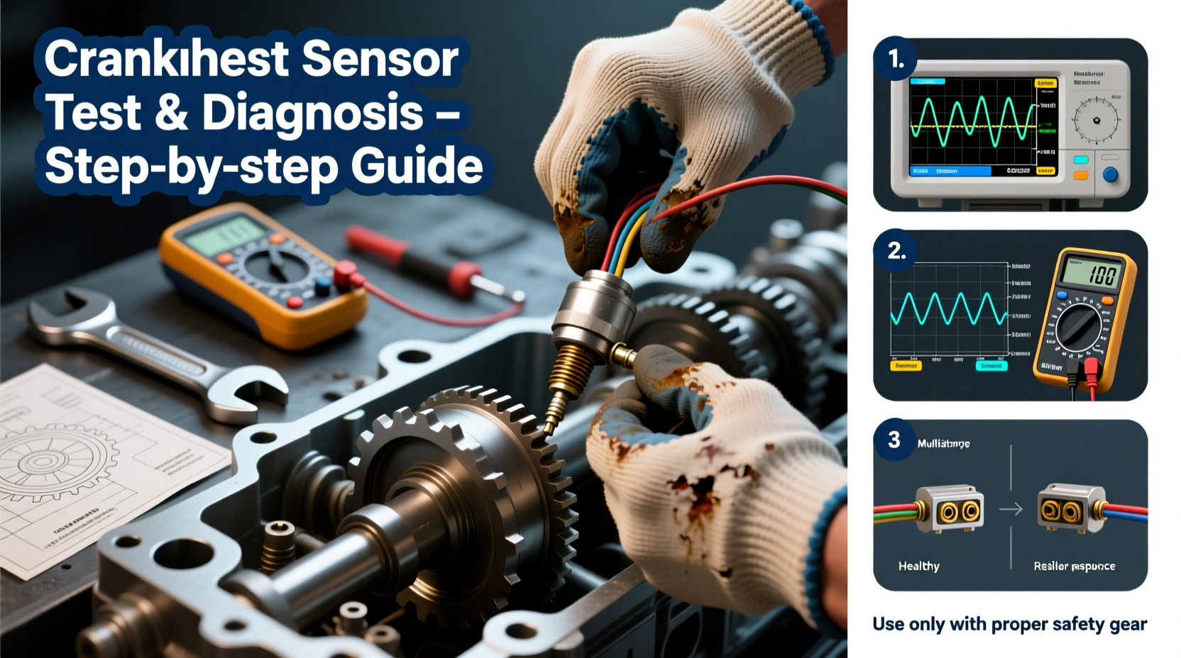
Step-by-Step Testing Procedure
Diagnosing a faulty crankshaft sensor requires a methodical approach. Follow these steps carefully to ensure accurate results and avoid misdiagnosis.
- Safety First: Disconnect the negative battery terminal before beginning work. The sensor is often located in tight, hot areas near moving engine components.
- Locate the Sensor: Refer to your vehicle’s service manual. Common locations include the front of the engine near the crankshaft pulley or at the rear near the transmission bellhousing.
- Inspect Wiring and Connectors: Check for damaged insulation, corrosion, or loose pins. Even if the sensor tests fine, faulty wiring can mimic sensor failure.
- Reconnect Battery and Set Up Multimeter: Use a digital multimeter set to AC voltage for magnetic sensors or DC voltage for Hall-effect types.
- Back-Probe the Signal Wire: With the sensor still connected, insert a pin into the back of the connector to access the signal circuit. Start the engine and observe the reading.
- Interpret Results:
- Magnetic Sensor: Expect an AC voltage between 0.5V and 5V that increases with engine speed.
- Hall-Effect Sensor: Should produce a clean digital signal switching between 0V and 5V or 12V.
- Check Reference Voltage and Ground: With the connector unplugged, verify that the sensor receives proper power (typically 5V or 12V) and has a solid ground connection.
Common Symptoms and Diagnostic Clues
Recognizing early signs of crankshaft sensor failure can prevent roadside breakdowns. While some symptoms overlap with other engine issues, certain patterns point directly to CKP problems.
| Symptom | Likely Cause | Differentiation Tips |
|---|---|---|
| Engine cranks but won’t start | Faulty CKP signal | No spark or injector pulse; check with scan tool |
| Intermittent stalling | Intermittent sensor contact | Occurs under load or after engine warms up |
| Rough idle or misfires | Inaccurate position data | OBD-II codes like P0335 may appear |
| Decreased fuel efficiency | ECU compensating for bad input | Accompanied by long-term fuel trim adjustments |
When to Suspect Wiring Over Sensor Failure
Many technicians replace the sensor prematurely without checking the circuit. A broken wire, corroded connector, or short to ground can produce identical symptoms. Always perform a continuity and resistance check on the wiring harness. Use the service manual to identify pinouts and expected resistance values.
Real-World Diagnosis Example
A 2012 Honda Accord arrived at a repair shop with complaints of sudden stalling during highway driving. The owner reported that the engine would restart after waiting several minutes. Initial OBD-II scan revealed code P0335: “Crankshaft Position Sensor Circuit Malfunction.” The technician replaced the sensor, but the issue returned within two days.
Upon deeper inspection, the mechanic discovered that the wiring harness near the exhaust manifold had melted insulation, causing an intermittent short. After repairing the harness with high-temperature sleeving and rerouting it away from heat sources, the problem resolved completely. This case highlights why circuit testing is just as important as sensor evaluation.
Do’s and Don’ts of Crankshaft Sensor Maintenance
| Do’s | Don’ts |
|---|---|
| Use dielectric grease on electrical connectors to prevent moisture ingress | Ignore error codes—even intermittent ones |
| Clean the sensor mounting area of debris before installation | Force the sensor into place; improper seating alters air gap |
| Verify air gap with a feeler gauge if specified by manufacturer | Use aftermarket sensors without verifying OEM specifications |
| Double-check wiring routing to avoid contact with hot or moving parts | Assume a new sensor is always good—defects do occur |
Essential Tools and Checklist
To successfully test and diagnose a crankshaft position sensor, gather the following tools beforehand:
- Digital multimeter (with AC and DC voltage settings)
- OBD-II scan tool
- Vehicle-specific service manual
- Pin-type back-probes or thin-gauge wire for signal testing
- Feeler gauge (if air gap specification exists)
- Basic hand tools (wrenches, sockets, screwdrivers)
Diagnostic Checklist
- Retrieve and record all stored OBD-II codes.
- Visually inspect sensor and wiring for damage.
- Test reference voltage at the sensor connector.
- Verify ground circuit integrity.
- Measure output signal while cranking or running.
- Compare readings to manufacturer specifications.
- Inspect reluctor wheel for missing or damaged teeth.
- Clear codes and verify resolution after repair.
Frequently Asked Questions
Can a bad crankshaft sensor damage my engine?
No, a failing crankshaft sensor won’t cause direct mechanical damage. However, incorrect fuel and spark timing due to faulty data can lead to unburned fuel entering the exhaust system, potentially damaging the catalytic converter over time.
How long does a crankshaft sensor typically last?
Most sensors last between 100,000 and 150,000 miles under normal conditions. Exposure to excessive heat, oil leaks, or vibration can shorten lifespan significantly.
Is it safe to drive with a bad crankshaft sensor?
No. Once symptoms appear, continued driving risks unexpected stalling, especially in traffic. It’s best to diagnose and repair the issue promptly.
Final Thoughts and Action Steps
Testing a crankshaft position sensor doesn’t require advanced equipment—just attention to detail and a logical process. Many DIYers and technicians skip thorough diagnostics, leading to wasted money on unnecessary parts. By understanding how the sensor works, recognizing failure patterns, and applying systematic testing, you gain control over one of the most pivotal engine management components.
If you’ve experienced hesitation, stalling, or starting issues, don’t assume the worst. Begin with a scan tool, inspect the basics, and validate sensor performance with a multimeter. Whether you're maintaining your own vehicle or managing a repair shop, mastering this skill reduces downtime and increases reliability.


 浙公网安备
33010002000092号
浙公网安备
33010002000092号 浙B2-20120091-4
Comments
No comments yet. Why don't you start the discussion?