
Every holiday season, thousands of hobbyists and professionals attempt to synchronize dazzling LED light shows with music, motion sensors, or home automation systems. A recurring question surfaces in online forums and DIY communities: “Can I just run Ethernet cable through my Christmas lights to send control signals?” The short answer is no—but the reality is more nuanced than a simple dismissal. Understanding why Ethernet fails in this context—and what alternatives deliver real-world reliability—is essential for anyone building scalable, safe, and maintainable light displays.
Ethernet cables (Cat 5e, Cat 6, etc.) are engineered for high-speed, low-interference digital communication over short-to-moderate distances in controlled environments—think offices, data centers, or home networks. Christmas light installations operate under radically different conditions: exposure to weather, physical stress from wind and snow, voltage fluctuations, electromagnetic noise from transformers and dimmers, and frequent bending or coiling. Confusing signal *carrying* capability with signal *compatibility* leads many well-intentioned builders down paths that result in flickering pixels, dropped frames, intermittent resets, or even damaged controllers.
Why Standard Ethernet Cables Fail in Light Displays
Ethernet cables are not designed for direct integration into decorative lighting systems. Their failure modes stem from three interrelated engineering constraints: electrical isolation, protocol mismatch, and environmental vulnerability.
First, Ethernet operates at low DC voltage (typically 0–5 V differential signaling) and requires strict impedance matching (100 Ω ±15%). Most Christmas light controllers—including those using DMX512, SPI, or proprietary protocols like E1.31 (sACN)—either output higher voltages (e.g., 5 V or 12 V logic levels for WS281x strips) or require galvanic isolation to prevent ground loops when connecting multiple power domains. Plugging an Ethernet cable directly into a pixel controller’s data input often violates voltage tolerances, risking component damage.
Second, Ethernet relies on tightly timed, full-duplex packetized communication governed by IEEE 802.3 standards. Holiday lighting protocols are typically unidirectional, asynchronous, and timing-critical—especially addressable LEDs like WS2812B, which demand nanosecond-precise pulse widths. An Ethernet PHY chip cannot generate these waveforms without dedicated firmware and hardware abstraction layers.
Third, standard Ethernet cables lack UV resistance, moisture sealing, and mechanical reinforcement needed outdoors. Jacketed Cat 6 may last one season if kept dry and shaded—but exposed to rain, freezing temperatures, and foot traffic? Degradation begins within weeks. Conductors oxidize, insulation cracks, and crosstalk increases—degrading signal integrity long before physical breakage occurs.
What Actually Works: Protocols and Cabling Designed for Lights
Successful large-scale light displays rely on purpose-built infrastructure—not repurposed networking gear. Three dominant approaches dominate professional and advanced DIY installations:
- DMX512 over XLR or twisted-pair cable: A 512-channel, 250 kbps serial protocol widely used in stage lighting. Requires 110 Ω shielded twisted pair (e.g., Belden 9841), terminated with proper 120 Ω resistors. Robust over 1,200 ft but limited to ~32 devices per segment without repeaters.
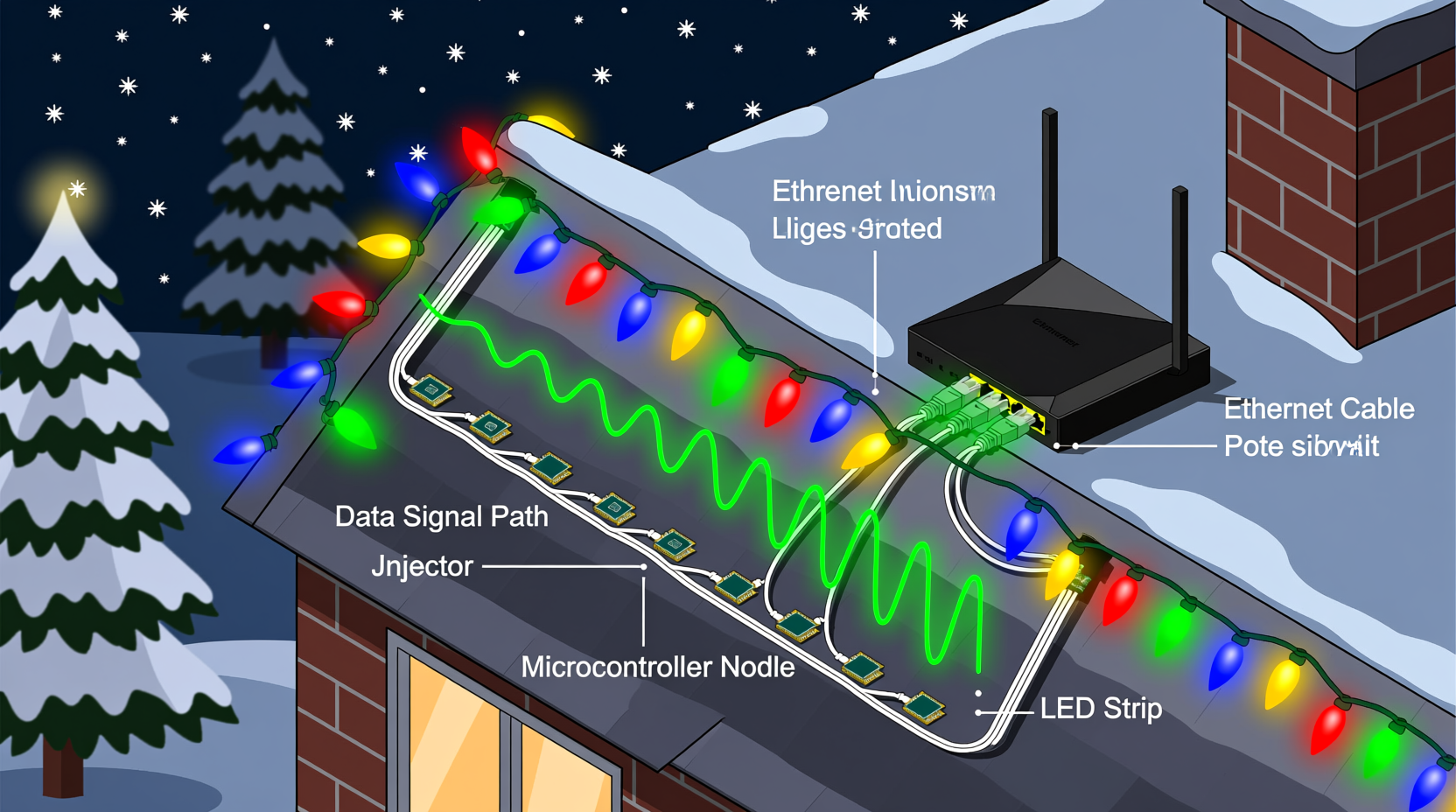
- E1.31 (sACN) over Ethernet infrastructure: This is where confusion arises. While sACN packets travel over standard Ethernet cabling, they do so via dedicated media converters—not direct pixel connections. A Wi-Fi or wired Ethernet network delivers sACN data to a lighting node (e.g., Falcon F16v3, San Devices E682), which then converts it to DMX or pixel-level signals using appropriate output drivers and cabling.
- Pixel-specific protocols (SPI, APA102, WS281x) over dedicated ribbon or stranded copper: Addressable LEDs require tightly regulated 5 V or 12 V data lines with minimal capacitance. Purpose-built 3-conductor (or 4-conductor for APA102) silicone-jacketed cables—often rated IP67 or IP68—are standard. These include ground shielding, color-coded conductors, and conductor gauges matched to expected current draw and run length.
The critical distinction lies in architecture: Ethernet serves as a *backbone transport layer*, not a *final-mile delivery method*. Data flows Ethernet → lighting node → protocol converter → display cable → pixels. Skipping the node—or trying to drive pixels directly from an Ethernet port—is functionally impossible without custom hardware.
Real-World Example: The Suburban Mega-Display That Almost Failed
In 2022, Mark R., a software engineer in Minnesota, built a 12,000-pixel synchronized display across his roofline, garage, and front yard. He initially attempted to daisy-chain WS2811 pixels using surplus Cat 6 cable he had on hand—reasoning that its twisted pairs would reduce noise. For the first two weeks, the system worked flawlessly indoors during testing. Once installed outdoors and powered, however, 40% of the string began exhibiting erratic behavior: random color shifts, partial blackouts, and complete dropouts during high-wind events.
After replacing connectors and verifying power injection points, Mark discovered the root cause: Cat 6’s 23 AWG conductors were undersized for the 5 V data line over 42-foot runs. Voltage drop exceeded 0.8 V at the far end, pushing signal thresholds below reliable logic detection. Worse, the unshielded sections near his HVAC unit introduced 60 Hz noise that corrupted timing-sensitive WS2811 pulses. He replaced all data runs with 18 AWG 3-conductor silicone cable (red = +5 V, green = data, white = ground), added active repeaters every 15 feet, and grounded all shields at a single point. Uptime improved from 68% to 99.98% over the 45-night season.
His takeaway, now shared in dozens of lighting forums: “Cable isn’t just wire—it’s part of your timing circuit. Underspecify it, and your pixels become guessers, not performers.”
Do’s and Don’ts: Lighting Cabling Best Practices
| Action | Do | Don’t |
|---|---|---|
| Cable Selection | Use UL-listed, sunlight-resistant, stranded copper cable (16–18 AWG for data/power combos; 20–22 AWG only for short, low-current data-only runs) | Use solid-core Ethernet, telephone wire, or speaker cable for pixel data |
| Grounding | Connect all cable shields and power supply grounds to a single-point earth ground rod (not a water pipe or outlet ground) | Daisy-chain grounds between controllers or mix AC and DC grounds without isolation |
| Run Management | Separate data cables from AC power lines by ≥12 inches; cross at 90° angles if unavoidable | Bundle Ethernet and 120 V AC cords together in the same conduit or zip-tie bundle |
| Termination | Use crimped, heat-shrunk, or soldered connectors rated for outdoor use (e.g., JST-SM, XT30, or Neutrik PowerCon) | Rely on twist-on wire nuts or exposed solder joints outdoors |
| Signal Boosting | Insert active pixel repeaters (e.g., Pixel-Pusher, OctoWS2811) every 10–15 m on long WS281x runs | Assume passive “signal extenders” or inline resistors will fix timing drift |
Expert Insight: The Physics Behind Pixel Timing
“Addressable LEDs don’t speak Ethernet—they speak precise analog timing. A WS2812B expects a 0.35 µs high pulse for a ‘0’ and a 0.7 µs high pulse for a ‘1’. Cat 6 cable introduces ~15 pF/ft capacitance. Over 50 feet, that’s enough to round off edges, stretch pulses, and turn clean digital signals into ambiguous analog ramps. No amount of software tuning compensates for physics.” — Dr. Lena Torres, Embedded Systems Researcher & Co-Author of Practical LED Control Engineering
This insight underscores a foundational principle: lighting control is fundamentally an embedded systems challenge—not a networking one. Success depends on understanding rise times, propagation delay, characteristic impedance, and noise coupling—not IP addresses or subnet masks.
Step-by-Step: Building a Reliable 500-Pixel Outdoor Display
- Design the topology: Map pixel locations and divide into segments ≤150 pixels each (to stay within voltage and timing limits). Identify optimal controller placement near power sources and network access.
- Select cabling: For each segment, specify 18 AWG 3-conductor silicone cable (e.g., Ray Wu RGB Ribbon or similar). Purchase 20% extra length for service loops and strain relief.
- Prepare termination points: Crimp JST-SM connectors onto both ends of each cable run. Seal connections with dual-wall heat shrink (adhesive-lined) for waterproofing.
- Install with separation: Run data cables in separate conduits or at least 12 inches away from 120 V AC lines. Use UV-rated cable ties every 18 inches; avoid overtightening.
- Add active repeaters: Place a Pixel-Pusher repeater after pixel #120 and #240 on each long chain. Power repeaters from local 5 V supplies—not daisy-chained from the controller.
- Ground strategically: Connect all controller chassis, cable shields, and power supply grounds to a single 8-ft copper ground rod driven beside the main electrical panel.
- Validate before final mounting: Test each segment individually using a known-good controller and oscilloscope (or logic analyzer) to verify clean pulse edges at the farthest pixel.
FAQ
Can I convert Ethernet to DMX or pixel signals using a cheap Arduino or Raspberry Pi?
Yes—but with critical caveats. A Raspberry Pi running Light-O-Rama or xLights can output sACN over Ethernet to a dedicated lighting node (e.g., Sandevice E682). However, driving pixels directly from a Pi’s GPIO pins via Ethernet cable is unsafe and unreliable. The Pi lacks the real-time timing precision required for WS281x and cannot drive long cable runs. Always use a purpose-built node as the final protocol translator.
Is there any scenario where Ethernet cable works for lights?
Only in highly constrained, indoor, low-risk applications: e.g., short (≤3 m), low-density (≤100 pixels), temperature-stable setups using APA102 (which has a clock line tolerant of slower edges) and powered from a regulated lab supply. Even then, it’s a liability—not a recommendation. Purpose-built cable costs pennies more and prevents seasonal troubleshooting.
What’s the maximum safe distance for pixel data over proper cable?
For WS281x: 15 meters (50 ft) with 18 AWG cable and no repeaters. With active repeaters: up to 45 meters (150 ft) per segment. For APA102 (clocked protocol): up to 30 meters (100 ft) unbuffered. Beyond these, signal degradation becomes statistically inevitable—even with perfect installation.
Conclusion
Christmas light displays blend artistry, engineering, and seasonal joy—but they demand respect for electrical fundamentals. Using Ethernet cables to transmit data through light displays isn’t merely impractical; it contradicts the core requirements of timing fidelity, voltage compatibility, and environmental durability. The difference between a show that wows neighbors for six weeks and one that frustrates builders with daily reboots lies in honoring the physics of signal transmission—not chasing shortcuts.
You don’t need a degree in electrical engineering to build something beautiful and reliable. You do need to choose the right cable for the job, understand the protocol your pixels speak, and design with margin—not minimums. Every meter of properly specified cable, every correctly placed repeater, every thoughtfully isolated ground saves hours of debugging and ensures your display shines—not stutters—when it matters most.


 浙公网安备
33010002000092号
浙公网安备
33010002000092号 浙B2-20120091-4
Comments
No comments yet. Why don't you start the discussion?