
Every holiday season, thousands of homeowners face the same frustrating ritual: dragging out last year’s lights, plugging them in—and watching only half the strand glow while the rest remains stubbornly dark. Rather than discarding the entire string or resorting to trial-and-error bulb swapping, experienced decorators and electricians rely on a precise, non-destructive method: continuity testing. This technique treats the light strand not as a mystery box of blinking bulbs but as a predictable series of electrical connections governed by Ohm’s Law and series circuit behavior. When a single bulb burns out, breaks its shunt, or develops an internal open, it can interrupt current flow for the entire section—especially in traditional 2-wire mini-light strands where bulbs are wired in series. A continuity tester (often built into a multimeter or available as a dedicated handheld tool) lets you map that break point without cutting a single wire, stripping insulation, or damaging the strand. This article details exactly how—grounded in real-world electrical principles, field-tested workflows, and practical safety awareness.
Why Continuity Testing Beats Guesswork (and Why Cutting Wires Is a Mistake)
Many DIYers default to “bulb-by-bulb” replacement or snipping wires near suspected failures. Both approaches waste time and introduce new risks. Removing bulbs disrupts the shunt path in older mini-lights—shunts are tiny resistive bridges designed to bypass a burnt filament and keep the rest of the circuit alive. If you remove a bulb before confirming whether its shunt is intact, you may inadvertently create an open circuit where none existed. Worse, cutting wires introduces moisture ingress points, insulation damage, and potential short circuits when reconnected with tape or twist-on connectors. A continuity test, by contrast, measures resistance across segments *while the strand remains fully assembled and unaltered*. It identifies opens—not just faulty bulbs, but broken wires, corroded sockets, cracked solder joints, or damaged plug terminals. The goal isn’t to find “the bad bulb”; it’s to locate the precise point where continuity fails, then intervene *only there*, preserving the integrity and longevity of the entire strand.
How Series Light Strands Actually Work (and Where They Fail)
Most incandescent mini-light strands (especially those manufactured before 2015) operate as series circuits: current flows from the plug’s hot wire through each bulb’s filament, then returns via the neutral wire. Each bulb has a parallel shunt—a thin nickel-chromium wire wrapped around the filament supports. When the filament burns out, voltage across that bulb rises, causing the shunt to heat up, melt its insulation, and fuse closed—bypassing the open filament and restoring continuity downstream. But shunts fail too: they can oxidize, corrode, or never activate if voltage doesn’t spike sufficiently (e.g., in low-voltage or partially failed strands). Modern LED strands often use series-parallel hybrid designs or constant-current drivers, making continuity testing more nuanced—but the core principle holds: an open anywhere in the current path stops illumination for dependent sections.
The key insight? A strand isn’t one continuous loop—it’s segmented. In a typical 100-light strand, manufacturers divide the circuit into sub-sections (e.g., 25-light groups), each protected by its own shunt network or fuse. That segmentation means a failure in one group rarely kills the whole string—but it does kill everything *after* the break point in that group. Continuity testing reveals exactly which segment contains the fault.
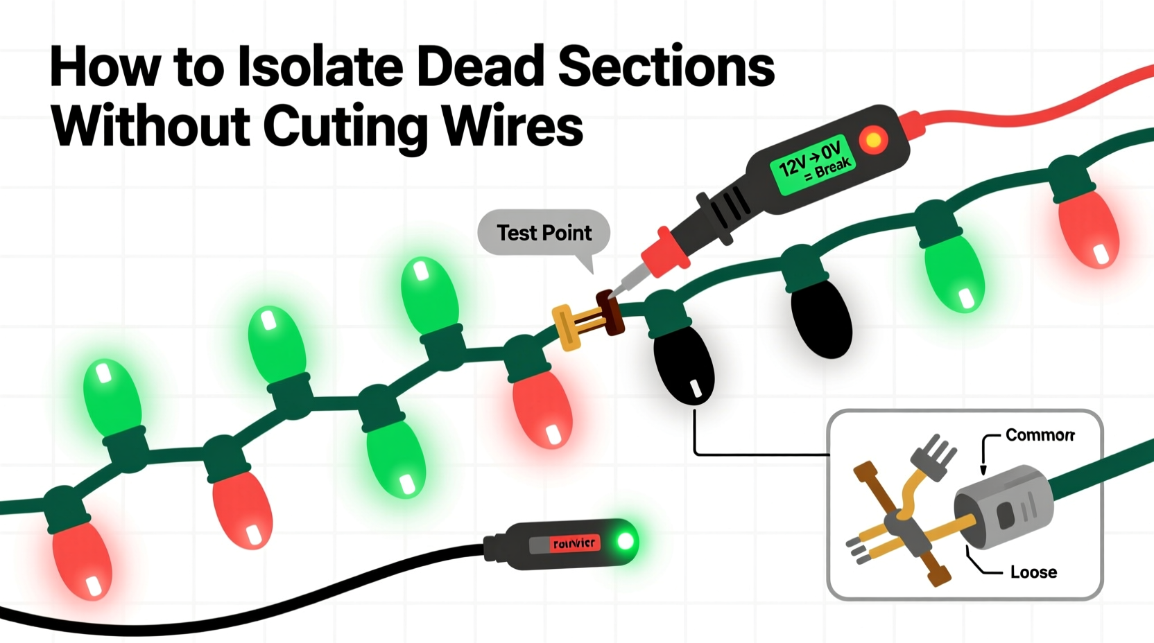
Step-by-Step: Isolating Dead Sections Without Cutting Wires
- Unplug and inspect visually: Check the plug for bent prongs, melted plastic, or scorch marks. Examine the first 3–5 inches of cord for kinks, cuts, or chew marks (common in outdoor storage). Note any visibly blackened, swollen, or discolored bulbs—they’re likely candidates but not guaranteed culprits.
- Set your multimeter to continuity or lowest ohms setting: Touch the probes together to confirm a clear beep or near-zero reading (0.2–0.5 Ω). If no beep, check battery and probe connection.
- Test the plug contacts: Place one probe on the narrow (hot) blade contact inside the plug and the other on the wide (neutral) blade contact. You should read high resistance or no continuity (open)—this confirms the circuit isn’t shorted at the source. Then test each blade to its corresponding wire end at the farthest socket: continuity here verifies wire integrity from plug to end.
- Divide and conquer with the “half-split” method: Starting at the plug, locate the midpoint socket (e.g., socket #50 on a 100-light strand). Insert one probe into the hot-side contact of that socket (usually the smaller slot or brass screw terminal), and the other probe into the neutral-side contact. If continuity beeps, the break is downstream (beyond socket #50). If silent, the break is upstream (between plug and socket #50). Repeat this halving process until you narrow the fault to a 3–5 bulb range.
- Test individual bulb sockets: With probes set to continuity, touch one probe to the metal tab at the bottom of a suspect socket (hot side) and the other to the threaded shell (neutral side). A working socket with an intact shunt will show low resistance (~1–5 Ω). An open socket reads OL (overload) or infinite resistance. If the socket tests open, gently wiggle the bulb—if resistance drops, the issue is poor contact, not a dead shunt.
- Verify shunt activation: Remove the bulb. Set multimeter to continuity. Touch probes to the two metal contacts *inside the empty socket* (not the bulb pins). A functional shunt will beep. No beep means the shunt is fused open or corroded—and that socket is the failure point.
Essential Tools and What They Reveal
A basic digital multimeter (DMM) is sufficient, but understanding what each mode tells you prevents misdiagnosis. Below is a comparison of common test modes and their interpretation for light strands:
| Test Mode | What You’re Measuring | Expected Reading (Good Strand) | What It Indicates If Abnormal |
|---|---|---|---|
| Continuity (Beep) | Low-resistance path between two points | Clear audible beep; <10 Ω | No beep = open circuit (broken wire, dead shunt, detached solder) |
| Resistance (Ω) | Exact resistance value | 1–5 Ω per functional socket (shunt active); ~100–200 Ω per live bulb filament | OL = open; 0 Ω = short (rare, but possible with melted insulation) |
| Voltage (AC) | Live voltage at socket under power | ~120 V at plug; drops incrementally down strand (e.g., 60 V at midpoint) | No voltage downstream of a point = open upstream; full voltage = open at that socket |
| Diode Test | Forward bias of LED chips (LED strands only) | Faint glow + 0.6–2.8 V drop (varies by color) | No glow + OL = dead LED or open connection; 0 V = shorted LED |
Note: Voltage testing requires powering the strand—only attempt with GFCI-protected outlets and insulated probes. For safety and simplicity, stick to continuity/resistance testing for initial diagnosis.
Mini Case Study: The Garage-Stored 200-Light Icicle Strand
Mark, a property manager in Ohio, stored 12 identical 200-light icicle strands in plastic bins in his unheated garage over winter. In November, he plugged in one strand: only the first 72 lights illuminated. He tried swapping bulbs in the dark section—no change. He cut the cord after the 72nd light, stripped wires, and connected them with a wire nut. The strand lit—but failed again after 4 hours, with smoke near the splice. Frustrated, he brought it to a local lighting repair shop. Technician Lena used a Fluke 117 multimeter in continuity mode. She started at the plug: continuity confirmed to socket #100. At socket #150: no beep. Halfway between (#125): beep. Between #137 and #143: silence at #140. She removed bulb #140—socket tested open. She cleaned the contacts with isopropyl alcohol and a soft brush, reinserted the bulb, and retested: continuity restored. The strand lit fully. Lena explained that cold-induced condensation had corroded the shunt contacts inside socket #140—not the bulb itself. Cutting the wire hadn’t fixed the root cause; it had merely created a new failure point. Mark applied contact cleaner to all 12 strands’ first 20 sockets before storage next year—and reported zero failures in December.
Expert Insight: The Physics Behind Reliable Diagnosis
“Continuity testing works because electricity follows the path of least resistance—but only if that path exists. A corroded shunt isn’t ‘high resistance’; it’s an insulator. Your meter doesn’t lie about opens—it reveals where the intended conductive path has been physically interrupted. Trust the measurement, not the bulb’s appearance.” — Carlos Mendez, Electrical Engineer & Holiday Lighting Consultant, National Lighting Association
Do’s and Don’ts of Strand Troubleshooting
- Do label sockets with masking tape and numbers before testing—especially on long or complex strands (net lights, curtain lights).
- Do clean socket contacts with 91% isopropyl alcohol and a cotton swab before final verification—even if continuity restores temporarily, oxidation will return.
- Do test multiple strands from the same batch simultaneously; shared storage conditions mean failures often cluster in the same socket position.
- Don’t assume the first dark bulb is the problem—shunts can fail silently in earlier sockets, starving downstream lights.
- Don’t use needle-nose pliers to force bulbs in or out; bent contacts increase resistance and mimic open-circuit symptoms.
- Don’t ignore the plug—even if the strand lights, a loose neutral connection causes intermittent flickering and premature shunt failure.
FAQ
Can I use a continuity tester on LED light strands?
Yes—but interpret results carefully. Most LED mini-strands use rectified AC and constant-current ICs. A continuity beep at a socket doesn’t guarantee the LED chip is functional; it only confirms the shunt or parallel path is intact. For LEDs, combine continuity testing with diode mode (to verify chip forward voltage) and visual inspection for cracked epoxy lenses or charred PCB traces.
My multimeter shows continuity, but the lights still don’t work. What’s wrong?
You’re likely measuring across a *shorted* section—not an open one. A short (e.g., nicked insulation bridging hot/neutral wires) creates a near-zero Ω path that steals current from the bulbs. Confirm by checking voltage drop: if you measure 120 V at the plug but 0 V at the first socket, a short exists in the cord before the first bulb. Inspect the cord for punctures or crushing.
Is there a faster way than half-splitting for very long strands?
Yes—use voltage gradient mapping. With the strand powered (via GFCI outlet), measure AC voltage at sequential sockets starting from the plug. Voltage should decrease steadily (e.g., 120 V → 110 V → 100 V). A sudden jump (e.g., 120 V → 120 V → 0 V) pinpoints the open: the socket showing full voltage but no downstream voltage is immediately upstream of the break.
Conclusion
Mastering continuity testing transforms holiday light maintenance from a seasonal chore into a repeatable, confident skill. It replaces frustration with precision, waste with preservation, and guesswork with grounded electrical understanding. You don’t need expensive gear—just a $20 multimeter, 15 minutes, and the willingness to follow the electrons instead of the blinking lights. Every strand you rescue extends its usable life, reduces holiday landfill waste, and saves money on replacements. More importantly, it builds competence that transfers to other household electrical tasks: testing doorbell wiring, diagnosing appliance faults, or verifying ground continuity in outdoor outlets. This isn’t just about lights—it’s about reclaiming control over the invisible systems that power our homes. So this season, before you reach for the wire cutters or the trash bag, grab your meter, start at the plug, and listen for that beep. The answer is already there—you just need to ask the right question.


 浙公网安备
33010002000092号
浙公网安备
33010002000092号 浙B2-20120091-4
Comments
No comments yet. Why don't you start the discussion?