
Bench testing an alternator is a critical diagnostic procedure for verifying its output, voltage regulation, and overall health outside of the vehicle. Whether you're a technician troubleshooting a charging system issue or a DIY enthusiast rebuilding components, accurate bench testing ensures reliability and prevents premature failure. Done incorrectly, it can lead to false readings, damaged equipment, or even personal injury. This guide walks through the essential steps, tools, and best practices to achieve consistent, trustworthy results when bench testing an alternator.
Why Bench Testing Matters
An alternator’s primary role is to recharge the battery and power electrical systems while the engine runs. When performance declines, symptoms like dim lights, slow cranking, or warning lights appear. While in-vehicle tests offer preliminary insights, they can be influenced by wiring resistance, belt tension, or battery condition. A bench test isolates the alternator from these variables, allowing for precise evaluation under controlled conditions.
Manufacturers often use bench testing during production and remanufacturing to validate output against specifications. For repair professionals, this method confirms whether an alternator should be rebuilt, replaced, or returned to service confidently.
“Bench testing removes real-world variables and gives you a true picture of an alternator’s capability.” — Carlos Mendez, Automotive Electrical Systems Engineer
Essential Tools and Setup Requirements
To conduct a valid bench test, you need more than just a multimeter. Proper instrumentation ensures accuracy and safety. Below is a checklist of required tools:
- Digital multimeter (capable of measuring DC voltage and amperage)
- 12-volt battery (fully charged, known good condition)
- Bench-mounted drill or variable-speed motor with compatible pulley
- Jumper wires with alligator clips (rated for at least 30A)
- Resistive load bank or high-wattage automotive bulbs (e.g., 55W–100W)
- Safety gloves and eye protection
- Voltage regulator tester (if external regulation is used)
The test environment should be clean, dry, and well-ventilated. Secure the alternator firmly in a vise with protective jaws to prevent damage to the housing. Never clamp directly on aluminum end bells.
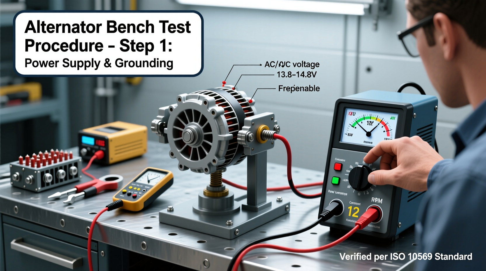
Step-by-Step Bench Testing Procedure
Follow this sequence carefully to obtain reliable data. Skipping steps may result in misleading readings or component damage.
- Inspect the Alternator Visually: Check for oil contamination, bearing play, cracked housing, or worn brushes. Replace seals or brushes if necessary before testing.
- Connect the Battery: Use heavy-gauge jumper wires to connect the battery positive (+) terminal to the alternator’s output stud (B+). Connect the negative (-) terminal to the alternator case (ground).
- Excite the Field Circuit: Apply 12V to the “F” (field) terminal using a fused wire from the battery positive. On internally regulated units, this is often done via the “L” or “IG” terminal depending on design. This primes the rotor windings.
- Attach Measuring Devices: Set your multimeter to DC volts. Place probes across the B+ and ground terminals. For amperage, use a clamp meter around the output cable or insert a shunt if available.
- Drive the Alternator: Use a drill or motor to spin the pulley. Start at approximately 1,500 RPM (use a tachometer if possible), then increase to 6,000 RPM—the typical maximum operating speed.
- Measure No-Load Voltage: At 1,500 RPM, voltage should reach at least 13.5V. By 6,000 RPM, it should stabilize between 13.8V and 14.7V. Excessive or low voltage indicates regulator issues.
- Apply Load and Measure Output: Introduce a resistive load (e.g., two 60W headlights in parallel). Recheck voltage and current. A healthy alternator should maintain voltage above 13.0V while delivering near its rated amperage (e.g., 90A for a 100A unit under partial load).
- Monitor Ripple Voltage (Optional): Using an oscilloscope, check AC ripple at the battery terminal. More than 0.5V AC suggests diode trio failure.
Interpreting Results: What the Numbers Mean
Understanding specifications is key. Refer to the OEM or manufacturer’s datasheet for exact values. The table below outlines acceptable performance ranges for common alternators:
| Parameter | Acceptable Range | Red Flag |
|---|---|---|
| No-load Voltage @ 1,500 RPM | 13.5V – 14.7V | <13.0V or >15.0V |
| Regulated Voltage @ Full Speed | 13.8V – 14.7V | Fluctuates or drifts over time |
| Full Output Current (Rated) | ≥90% of rated amps | <70% of rating under load |
| Ripple Voltage (AC) | <0.5V AC | >1.0V AC |
| Bearing Noise/Play | No audible noise, minimal axial/radial movement | Grinding, wobble, or looseness |
If voltage fails to build, check brush continuity and slip ring contact. Low output under load often points to failed diodes, stator windings, or insufficient drive speed.
Common Mistakes and How to Avoid Them
Even experienced technicians make errors that compromise test validity. Here are frequent pitfalls:
- Using undersized jumper wires: Thin cables create voltage drop, skewing readings. Use 6 AWG or larger for high-current paths.
- Inadequate drive speed: Alternators require minimum RPM (often 1,500–2,000) to generate useful output. Drilling too slowly yields false \"failure\" diagnosis.
- Testing without load: Regulators behave differently under load. Always verify performance with a realistic electrical demand.
- Ignoring temperature: Overheating during extended testing can temporarily reduce output. Allow cooling intervals if testing beyond 2 minutes continuously.
- Assuming internal regulation works universally: Some modern alternators use PWM control from the ECU. These may not self-excite on a bench without simulated vehicle signals.
“Most ‘bad’ alternators we get tested turn out to have been misdiagnosed due to poor bench setup—not actual failure.” — Dana Reeves, Remanufacturing Lead, Apex Auto Electrics
Real-World Example: Diagnosing a Misdiagnosed Unit
A technician brought in a 120A alternator from a delivery van, labeled “no output.” Initial bench test showed only 11.8V at 2,000 RPM. Suspecting stator failure, he was about to scrap it. However, upon checking connections, he found the field wire had a cold solder joint. After resoldering and retesting with proper excitation, the unit produced 14.2V no-load and 118A under load—within spec. The issue wasn’t the alternator, but faulty bench wiring. This saved the shop $280 in replacement costs.
This case highlights how procedural precision impacts outcomes. A few seconds spent verifying connections prevented a costly error.
Frequently Asked Questions
Can I bench test an alternator without a battery?
No. The battery stabilizes voltage and provides initial excitation current. Attempting to run an alternator without a battery risks damaging the internal regulator due to unstable back-EMF.
Why does my alternator produce voltage but fail under load?
This typically indicates failing diodes or a damaged stator winding. Under load, one or more phases may drop out, reducing total output. Perform a ripple test or stator resistance check to confirm.
Do modern smart-charging alternators work on a standard bench?
Not always. Many late-model vehicles use variable voltage control via CAN bus communication. These units may default to low-output mode without ECU signals. Specialized testers or simulation modules are needed for full evaluation.
Final Thoughts and Action Steps
Accurate bench testing separates guesswork from diagnosis. With the right tools, attention to detail, and understanding of electrical fundamentals, anyone can validate alternator performance reliably. Remember: consistency in setup, adherence to safety protocols, and interpretation based on specs—not assumptions—are what deliver trustworthy results.


 浙公网安备
33010002000092号
浙公网安备
33010002000092号 浙B2-20120091-4
Comments
No comments yet. Why don't you start the discussion?