
Decorating for the holidays often means balancing brightness, color schemes, and energy use across multiple rooms. A single power strip or timer won’t give you the control needed when managing lights in a living room, dining area, hallway, and staircase. That’s where a modular Christmas tree light controller comes in — a custom-built system that allows independent control of lighting zones using programmable logic, remote access, and even voice commands.
This guide walks through building a scalable, reusable controller using affordable components like microcontrollers, relays, and open-source firmware. Whether you’re illuminating a single tree or an entire home display, this system offers precision, safety, and seasonal reusability.
Why Go Modular?
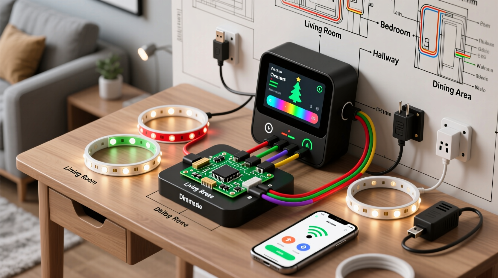
A traditional string of Christmas lights plugs into one outlet and operates all-or-nothing. But modern holiday displays benefit from segmentation: warm white on the tree, multicolor on the mantle, and dimmable blue along the banister. Each zone may require different timing, brightness, or animation patterns.
A modular controller separates these functions into distinct circuits, each managed by software. This approach enables:
- Individual on/off scheduling per room
- Different lighting effects (fading, twinkling, pulsing)
- Energy savings by turning off unused zones
- Integration with smart home platforms like Home Assistant or Alexa
- Reusability year after year with minimal rewiring
Core Components and Tools
Building a modular controller requires both electronic components and basic tools. Most items are available from electronics retailers or online marketplaces.
| Component | Purpose | Recommended Example |
|---|---|---|
| Microcontroller | Brains of the system; runs control logic | ESP32 or ESP8266 (Wi-Fi + Bluetooth support) |
| Relay Module (4–8 channel) | Switches high-voltage AC circuits safely | Opto-isolated 5V relay board |
| Power Supply | Provides stable 5V DC to microcontroller and relays | 120VAC to 5VDC adapter (2A minimum) |
| Enclosure Box | Houses electronics safely | Plastic project box with mounting rails |
| AC Outlets or Terminal Blocks | Connects to actual light strings | Screw terminal strips or switched outlets |
| Jumper Wires & Connectors | Internal circuit connections | M/F and F/F dupont cables |
| Optional: LED Strip Driver | For addressable RGB (e.g., WS2812B) lights | Separate MOSFET or dedicated driver board |
In addition to parts, gather tools such as wire strippers, a soldering iron, multimeter, screwdrivers, and electrical tape. Safety first: always disconnect power before working on any circuit.
Step-by-Step Assembly Guide
Follow this sequence to build your modular controller safely and effectively.
- Design Your Zone Layout: Map out which rooms or areas will have independent control. Assign names like “Tree Top,” “Staircase Rails,” or “Dining Table.” Decide how many zones you need — typically 4 to 8 for most homes.
- Wire the Relay Module: Connect each relay output to a separate AC outlet or terminal block. Ensure hot (black) wires pass through the relay’s switch contact, while neutral (white) and ground (green) go directly to the outlet. Never switch neutral lines — only hot.
- Connect Control Signals: Link the IN pins of the relay module to digital GPIO pins on the ESP32. For example:
- GPIO 12 → Zone 1
- GPIO 13 → Zone 2
- ... up to 8 zones if supported
- Power the System: Wire the 120V input to both the relay common terminals and the DC power supply. The power supply steps down voltage to 5V for the microcontroller. Use insulated connectors and strain relief clamps.
- Secure Inside Enclosure: Mount the relay board, ESP32, and power supply inside the project box. Leave space for airflow and cable management. Seal unused openings with rubber grommets.
- Test Each Zone Individually: Before final installation, power up the system and test each relay using simple code to toggle outputs. Confirm that lights turn on/off correctly without arcing or overheating.
Programming the Controller
The real power lies in software. Using the Arduino IDE or PlatformIO, write firmware that defines behavior for each zone.
Sample logic includes:
- Turn on living room lights at sunset, fade over 30 minutes
- Run staircase LEDs in sequence every evening from 5 PM to 10 PM
- Disable all zones after January 7 unless manually overridden
Here’s a simplified code snippet using the ESP32 and NTP time synchronization:
#include <WiFi.h>
#include <NTPClient.h>
#include <WiFiUdp.h>

const char* ssid = \"your_wifi_ssid\";
const char* password = \"your_wifi_password\";

WiFiUDP ntpUDP;
NTPClient timeClient(ntpUDP, \"pool.ntp.org\", -5 * 3600); // EST

int zonePins[] = {12, 13, 14, 15}; // GPIO pins for relays
int sunriseHour = 7, sunsetHour = 17;

void setup() {
  Serial.begin(115200);
  WiFi.begin(ssid, password);
  while (WiFi.status() != WL_CONNECTED) delay(500);

  timeClient.begin();
  timeClient.update();

  for (int i = 0; i < 4; i++) {
    pinMode(zonePins[i], OUTPUT);
    digitalWrite(zonePins[i], HIGH); // Relays OFF (active-low)
  }
}

void loop() {
  timeClient.update();
  int currentHour = timeClient.getHours();

  // Living Room Tree: On from 5 PM to 10 PM
  digitalWrite(zonePins[0], (currentHour >= 17 && currentHour < 22) ? LOW : HIGH);

  // Staircase: On from 6 PM to 9 PM
  digitalWrite(zonePins[1], (currentHour >= 18 && currentHour < 21) ? LOW : HIGH);

  delay(60000); // Check every minute
}
For advanced users, integrate MQTT to publish state changes to a central hub or allow remote override via mobile app. Libraries like PubSubClient make this seamless.
“Modular lighting isn’t just about aesthetics — it’s about intelligent resource management. A well-designed controller can reduce holiday energy consumption by up to 40%.” — Dr. Alan Reyes, Smart Grid Researcher, MIT Energy Initiative
Real-World Application: The Johnson Family Setup
The Johnsons live in a two-story colonial with a formal living room, open kitchen, front porch, and winding staircase. Each year, they struggled with tangled cords and inconsistent schedules.
Last season, they built a 6-zone modular controller using an ESP32 and dual 4-channel relay boards. Zones included:
- Zone 1: Tree (living room)
- Zone 2: Mantle garland
- Zone 3: Stair railing wraps
- Zone 4: Kitchen island pendants
- Zone 5: Porch columns
- Zone 6: Dining table centerpiece
They programmed the system to activate outdoor lights earlier (dusk), interior lights later (6 PM), and disable everything after 10:30 PM. By integrating with Google Assistant, family members could say, “Turn on the tree,” without touching a switch.
The result? A cohesive, elegant display with no manual intervention — and a 35% drop in December electricity usage compared to the previous year.
Checklist: Building Your Own Modular Controller
- ☐ Define number of lighting zones and their locations
- ☐ Choose microcontroller (ESP32 recommended for Wi-Fi/Bluetooth)
- ☐ Purchase appropriately rated relay module (check max load per channel)
- ☐ Acquire a UL-listed power supply and surge-protected enclosure
- ☐ Plan wiring paths and outlet placements
- ☐ Write or adapt control code with desired schedules
- ☐ Test all components individually before final assembly
- ☐ Label every zone clearly on the enclosure and in code
- ☐ Perform final safety inspection (no exposed conductors, secure mounts)
- ☐ Document setup for reuse next year
Frequently Asked Questions
Can I control this system remotely?
Yes. Once connected to Wi-Fi, the ESP32 can host a web server or connect to cloud services like Blynk, Home Assistant, or Node-RED. You can then control zones via smartphone, tablet, or voice assistant.
Is it safe to build my own light controller?
Yes, provided you follow electrical safety practices. Always use opto-isolated relays, enclose high-voltage components, and avoid working on live circuits. If unsure, consult a licensed electrician for the AC wiring portion.
Can I add more zones later?
Absolutely. The modular design supports expansion. Use multiple relay boards daisy-chained via I2C or additional GPIO pins. Just ensure your power supply can handle the increased load on the control side.
Final Thoughts and Next Steps
A modular Christmas tree light controller transforms holiday decorating from chaotic to curated. It replaces guesswork with precision, clutter with clarity, and wasted energy with thoughtful automation.
Start small — perhaps just two zones this year — and expand as you gain confidence. Reuse the same core unit annually by storing it properly in a dry, temperature-stable location. Update the firmware each season to refine timing or add new effects.
The technology is accessible, the cost is low, and the impact is immediate. More than just blinking lights, this project blends craftsmanship, efficiency, and festive spirit into one functional piece of holiday engineering.


 浙公网安备
33010002000092号
浙公网安备
33010002000092号 浙B2-20120091-4
Comments
No comments yet. Why don't you start the discussion?