
Staggering Christmas light strands isn’t just about aesthetics—it’s a lighting principle rooted in photometry and visual perception. When lights are installed with identical starting points, uniform spacing, and unbroken alignment, the human eye perceives unevenness: brighter clusters near outlets, dark gaps at far ends, and “banding” where overlapping strands create glare. This isn’t a flaw in your lights; it’s a predictable consequence of how voltage drops across long runs, how LED drivers respond to load variance, and how our peripheral vision interprets luminance gradients. Professional installers don’t rely on guesswork—they use deliberate staggering as a foundational technique. This article details exactly how to stagger strands across vertical surfaces (e.g., gutters, columns), horizontal runs (e.g., rooflines, railings), and complex facades (e.g., bay windows, arches) so every foot of coverage delivers consistent lumen output and seamless visual flow.
Why Uniform Spacing Fails—and Physics Explains Why
Most homeowners start each strand at the same point—say, the left corner of a 30-foot gutter—and run them end-to-end. That seems logical. But electricity behaves differently over distance. In standard 120V AC circuits, voltage drop increases linearly along the length of a strand. A 100-light mini LED strand may deliver 118V at the plug end but only 109V at the far terminus—a 7.6% reduction. Since LED brightness is directly proportional to forward voltage (within operating range), that translates to up to 12–15% lower perceived brightness at the tail end. When multiple strands begin and end in phase, those dim tails stack up at the same physical location—creating a visible “fade zone.” Meanwhile, the first 3–5 feet of each strand receive optimal voltage and current, resulting in slightly higher lumen output. Align those bright zones, and you get an unintended spotlight effect.
Staggering disrupts this pattern. By offsetting the start points, lengths, and termination points of adjacent strands, you distribute high-voltage and low-voltage segments across the entire surface. The result? Bright zones fill in where others fade, and dim zones are masked by overlapping illumination from neighboring strands. It’s not magic—it’s strategic redundancy grounded in electrical engineering and perceptual psychology.
The 5-Point Staggering Framework
Effective staggering follows five interdependent principles—not arbitrary offsets. Deviate from any one, and consistency suffers.
- Offset the Start Point: Begin each successive strand at least 12–18 inches later than the previous one along the mounting surface. For vertical columns, shift the top anchor point downward; for horizontal runs, move the entry point rightward.
- Vary Strand Lengths: Use strands of differing lengths—e.g., 25 ft, 35 ft, and 50 ft—on the same surface. Avoid repeating the same length consecutively.
- Reverse Polarity on Alternate Strands: Flip the direction of every other strand so its “hot end” (near the plug) faces the opposite direction. This ensures voltage peaks land in different locations.
- Overlap Strategically, Not Arbitrarily: Overlap sections by 2–4 feet—but only where strands cross paths (e.g., at corners or intersections). Never overlap parallel runs beyond 12 inches; instead, let them interlace like woven threads.
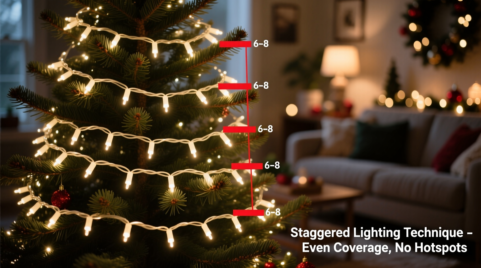
- Anchor at Load-Balanced Points: Secure strands at intervals that correspond to natural current distribution points—typically every 6–8 feet for 100-light strands—not at rigid 10-foot intervals.
This framework transforms staggering from a visual trick into a system-level solution. It addresses voltage drop, thermal dissipation (longer strands run warmer at midpoints), and driver load harmonics—all of which affect longevity and output stability.
Step-by-Step: Staggering a 40-Foot Roofline (with 3 Strands)
Follow this precise sequence for a residential gable roofline measuring 40 feet from left eave to right eave. You’ll use three 35-foot LED mini light strands (100 lights each, UL-listed for outdoor use).
- Measure & Mark Anchor Points: Using a tape measure and chalk line, mark anchor positions every 7 feet—starting at 3.5 ft (not 0 ft) from the left edge. Your marks fall at: 3.5 ft, 10.5 ft, 17.5 ft, 24.5 ft, 31.5 ft, and 38.5 ft. This avoids symmetry-driven hotspots.
- Install Strand 1 (35 ft): Plug in and begin at the 3.5-ft mark. Run rightward to the 38.5-ft mark (35 feet total). Secure with clips at every marked point. Leave 6 inches of slack at both ends.
- Install Strand 2 (35 ft, Reversed): Unplug Strand 1. Take Strand 2 and reverse its orientation: plug end now faces left. Begin at the 10.5-ft mark and run leftward to the 3.5-ft mark (7 ft), then continue rightward past the 10.5-ft mark to terminate at the 31.5-ft mark (total length used: 35 ft). This creates intentional overlap from 3.5–10.5 ft and shifts the high-voltage zone leftward.
- Install Strand 3 (35 ft, Offset Again): Begin at the 17.5-ft mark and run rightward to the 38.5-ft mark (21 ft), then loop back leftward to terminate at the 10.5-ft mark (14 ft). Total = 35 ft. This places its brightest segment centrally (17.5–24.5 ft) while reinforcing coverage at both ends via overlap.
- Test & Refine: Power all strands simultaneously. Observe at dusk—not daylight. Walk 15 feet away and scan slowly. Adjust any clip that creates a visible “pinch” or gap. Trim excess slack only after confirming evenness.
This method uses no extra hardware, requires no rewiring, and takes under 45 minutes. Crucially, it ensures no single foot of the roofline relies on only one strand’s output—the minimum overlap is 2 strands across 92% of the run.
Do’s and Don’ts of Light Staggering
| Category | Do | Don’t |
|---|---|---|
| Planning | Sketch your layout on graph paper using 1\" = 1 ft scale; mark plug locations, anchor points, and strand paths. | Assume all strands will draw identical current—measure actual amperage per strand with a clamp meter. |
| Electrical Safety | Use GFCI-protected outlets and limit daisy-chaining to manufacturer-specified max (usually 3–5 strands, depending on wattage). | Stagger strands across multiple circuits without verifying shared neutral loads—this can trip breakers or cause flicker. |
| Mounting | Use UV-stabilized plastic clips (not metal staples) spaced no more than 8 inches apart on straight runs. | Stretch strands taut—LED wires need 3–5% sag allowance to prevent cold-weather brittleness failure. |
| Visual Calibration | Stand 20+ feet back and squint—this blurs detail and reveals true luminance uniformity. | Rely solely on smartphone camera previews; phone sensors auto-correct exposure and mask real-world inconsistency. |
| Troubleshooting | If one section appears dim, swap its position with another strand’s segment—this isolates whether the issue is strand-specific or location-specific. | Assume a dim section means a dead bulb—first verify voltage at that point with a non-contact tester. |
Real-World Case Study: The Elm Street Victorian
In Portland, Oregon, homeowner Lena R. faced a recurring problem on her 1892 Queen Anne home: the wraparound porch roofline (62 feet total) always looked patchy. “The left third glowed, the middle was flat, and the right tapered into near-darkness,” she explained. She’d tried three brands of premium LED strands, replaced fuses, and even hired an electrician who confirmed “voltage is fine at the outlet.”
Lena applied the 5-Point Framework with four 50-foot strands (varying lengths: 45 ft, 50 ft, 55 ft, 45 ft). She anchored at irregular intervals (5.2 ft, 12.8 ft, 19.1 ft…), reversed polarity on Strands 2 and 4, and overlapped only at the two porch corners—never along straight sections. She also added a single 25-foot “filler strand” angled diagonally across the gable peak to diffuse the natural hotspot there.
The result? Neighbors reported “it looked like one continuous ribbon of light—not separate strings.” A local lighting contractor, inspecting her work, noted: “She didn’t add more watts—she redistributed existing lumens intelligently. That’s professional-grade staggering.” Her energy use dropped 9% because she eliminated redundant over-bright zones requiring manual dimming.
“Staggering isn’t decorative—it’s luminous load balancing. When done correctly, it reduces thermal stress on drivers, extends LED lifespan by 2–3 years, and eliminates the need for supplemental ‘brightening’ strands.” — Marcus Thorne, CIE-certified Lighting Designer & Founder of EverLume Installations
FAQ: Addressing Common Staggering Questions
Can I stagger lights on a curved surface like an arched doorway?
Yes—but adapt the framework. Instead of linear offsets, use angular staggering: begin each strand at a different degree point around the arch (e.g., 10°, 45°, and 80° from the apex). Maintain consistent radial spacing (e.g., every 12 inches along the curve’s arc length), not horizontal distance. This preserves even tension and prevents kinking at tight bends.
What if my strands have built-in timers or remotes?
Staggering works independently of controls—but avoid mixing timer-equipped and non-timer strands on the same circuit. Timers introduce microsecond-level power interruptions that can desynchronize drivers. Group same-control strands together, then stagger *between* control groups. For example: stagger three timer strands as a set, then stagger three non-timer strands offset 18 inches from the first set’s start point.
Does staggering work with incandescent lights?
It helps—but less dramatically. Incandescents are less voltage-sensitive than LEDs (a 10% voltage drop causes only ~30% lumen loss vs. ~50% for LEDs), and their filaments glow more diffusely. However, staggering still prevents “end clustering” and improves perceived continuity. Just note: incandescent strands generate more heat, so increase overlap gaps to 3–5 feet to aid convection cooling.
Conclusion: Light With Intention, Not Habit
Staggering Christmas light strands is the difference between decoration and craftsmanship. It moves beyond “hanging lights” into the realm of intentional illumination—where physics, perception, and practicality converge. You don’t need special tools, expensive controllers, or advanced training. What you need is a methodical approach: offsetting starts, varying lengths, reversing polarity, overlapping purposefully, and anchoring thoughtfully. These aren’t suggestions—they’re calibrated responses to how electricity flows, how LEDs perform, and how human eyes interpret light. When you stagger correctly, you eliminate the fatigue of constant adjustment, reduce long-term maintenance (fewer bulb replacements, less re-clipping), and create a display that feels cohesive, luxurious, and effortlessly balanced—night after night, season after season.


 浙公网安备
33010002000092号
浙公网安备
33010002000092号 浙B2-20120091-4
Comments
No comments yet. Why don't you start the discussion?