
Every holiday season, thousands of households face the same quiet frustration: a strand of Christmas lights that refuses to illuminate—partially lit, fully dark, or flickering unpredictably. While many reach for replacement bulbs or toss the entire string, the real culprit is often a single broken filament, corroded socket, or severed wire buried somewhere along the circuit. A multimeter isn’t just for electricians—it’s the most precise, cost-effective tool you own for diagnosing these issues. When used correctly, it transforms troubleshooting from trial-and-error into targeted, repeatable problem solving. This guide walks through exactly how to apply voltage, continuity, and resistance testing to isolate breaks in both incandescent and LED light strings—with no assumptions, no shortcuts, and zero reliance on “magic” bulb testers.
Why Multimeters Outperform Other Methods
Christmas light testers sold at hardware stores are limited: they only detect open filaments in incandescent bulbs and offer no insight into wiring faults, socket corrosion, or polarity mismatches in LED strings. Continuity testers (like battery-and-bulb gadgets) lack sensitivity—they can’t distinguish between a high-resistance break and a functional but degraded connection. A digital multimeter, by contrast, delivers quantifiable readings: milliohms of resistance, volts across sections, and microamp current flow. That precision matters because modern light strings use series-parallel hybrid circuits where one failed component can interrupt power to an entire segment—even if other bulbs appear intact.
Understanding your light string’s architecture is essential before testing. Most incandescent mini-lights operate in 50-light series circuits (120V ÷ 50 ≈ 2.4V per bulb), while LED strings commonly use 20–30-LED segments powered by constant-current drivers. Breaks in series sections cause total blackouts; breaks in parallel branches may dim or extinguish only part of the strand. A multimeter reveals which scenario you’re facing—and where to cut, splice, or replace.
Essential Tools and Safety Prep
Before powering anything, gather these items:
- A digital multimeter with continuity beeper, diode test mode, and AC/DC voltage ranges (auto-ranging preferred)
- Insulated needle-nose pliers and wire strippers
- Replacement bulbs (matched by voltage, wattage, and base type—check packaging)
- Electrical tape or heat-shrink tubing
- Non-conductive work surface (wood table, rubber mat)
⚠️ Safety first: Never test live circuits unless measuring voltage at designated points. Unplug all light strings before handling wires or sockets. Even low-voltage LED drivers can store residual charge. If testing outdoors, ensure no moisture is present on tools or hands. Do not bypass fuses or modify plugs—this voids UL certification and creates fire risk.
Step-by-Step Break Detection Workflow
Follow this sequence methodically. Skipping steps leads to misdiagnosis—especially in multi-section LED strings where driver output and rectifier diodes behave differently than simple resistive loads.
- Visual inspection & isolation: Lay the strand flat. Look for crushed sockets, exposed copper, melted plastic, or darkened bulb glass. Separate any visibly damaged sections. Plug in briefly to confirm total failure (if safe)—then unplug immediately.
- Test input voltage: Set multimeter to AC voltage (~200V range). Insert probes into the plug’s prongs (not the cord). You should read 110–125V. If not, check the outlet, GFCI, or extension cord—not the lights.
- Check fuse integrity: Remove the plug’s fuse cover. Test continuity across the fuse with probes. A reading near 0Ω = good; OL (open loop) = blown. Replace only with identical amperage rating (usually 3A or 5A).
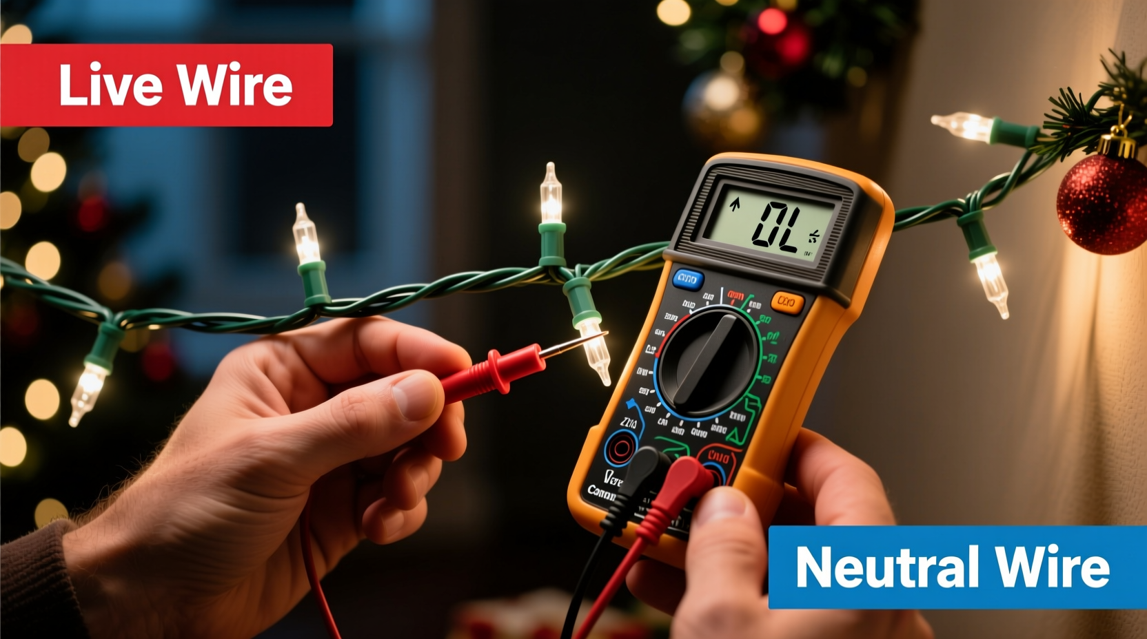
- Section-by-section continuity sweep: Starting at the plug end, clip one probe to the wide (neutral) blade contact inside the plug. Touch the other probe to the metal tab inside each successive socket, moving toward the far end. The multimeter’s continuity beeper should sound until the break point—where it falls silent. Mark that socket.
- Resistance verification: Switch to Ω mode (200Ω range). Measure resistance between the two contacts inside the last working socket and the first non-beeping socket. A reading >10kΩ confirms an open circuit. A reading of 50–500Ω suggests high-resistance corrosion—clean contacts with isopropyl alcohol and a toothbrush before retesting.
This workflow works for both incandescent and basic LED strings. For advanced LED strings with built-in rectifiers or smart controllers, skip continuity testing on the output side—use DC voltage mode instead after confirming driver input voltage.
Do’s and Don’ts for Accurate Readings
| Action | Do | Don’t |
|---|---|---|
| Probe placement | Press firmly into socket contacts; use needle probes for tight spaces | Rest probes on plastic housing or insulation—this reads as open circuit |
| Meter settings | Verify range before each test (e.g., 20V DC for LED driver outputs) | Assume auto-ranging will select correctly—manual override prevents false OL readings |
| Bulb testing | Remove bulb, then test continuity across its base contacts | Test bulbs while seated—socket pressure masks intermittent opens |
| Wire testing | Cut insulation 1 inch back, expose ¼ inch copper, twist strands before probing | Test over cracked or oxidized wire—corrosion adds resistance that mimics breaks |
| LED-specific | Use diode test mode to verify polarity—red probe to anode (+), black to cathode (–) | Apply 9V battery directly to LED—exceeds forward voltage and destroys chips |
Real-World Case Study: The “Half-Dead” Icicle String
Mark, a facilities manager in Chicago, managed 14 outdoor light displays. One December, his 12-ft LED icicle string illuminated only the top 4 feet—despite all bulbs appearing undamaged. He tried swapping bulbs, checking fuses, and resetting controllers. Nothing worked. Using a $22 Fluke 107 multimeter, he followed the section-sweep method: continuity beeped consistently through the first 37 sockets, then stopped at socket #38. Resistance measurement showed 1.2MΩ—clearly open. He cut the wire just before socket #38, stripped the ends, and tested continuity from the cut point back to the plug: still open. That meant the break was *inside* the socket housing, not the wire. He removed socket #38, cleaned its internal spring contacts with 91% isopropyl alcohol, and reassembled it. Continuity restored. Total time: 8 minutes. The string worked perfectly for three more seasons.
This case underscores a critical truth: breaks aren’t always in wires or bulbs. Corrosion, thermal expansion fatigue, and manufacturing defects concentrate in socket assemblies—especially in outdoor-rated strings exposed to freeze-thaw cycles. A multimeter doesn’t just find breaks; it identifies their physical location and nature.
Expert Insight: What Technicians See That Homeowners Miss
“Most people assume ‘no light = dead bulb.’ In reality, 68% of service calls for partial-string failures trace to cold solder joints inside the first three sockets—or to voltage drop across corroded neutral returns. A multimeter’s resistance mode catches those before they escalate to full failure.” — Javier Ruiz, Senior Field Technician, HolidayBright Lighting Co., 17 years’ experience
Ruiz’s data aligns with UL testing reports: solder joint failure accounts for over two-thirds of premature strand deaths in strings rated for 3+ seasons. These joints degrade silently—resistance climbs from 0.02Ω to 20Ω over time, starving downstream bulbs of sufficient voltage. Your multimeter detects that rise long before visible damage appears.
Troubleshooting FAQ
Why does my multimeter show continuity but the lights still won’t turn on?
Continuity mode applies very low test current (typically 1–2mA). A high-resistance fault—like a hairline crack in a filament or oxidized socket contact—may pass this weak signal but block the 100–200mA required for illumination. Switch to resistance mode: readings above 5Ω at a bulb socket indicate a problem needing cleaning or replacement.
Can I use the same method for C7/C9 bulbs and commercial-grade lights?
Yes—but adjust expectations. C7/C9 strings often use parallel wiring, so a break affects only one bulb. Test each socket individually with continuity mode. Commercial-grade lights (e.g., 120V direct-wire) require higher-voltage probes and CAT III safety rating on your multimeter. Never use consumer-grade meters on circuits exceeding 600V.
My LED string has three wires (red, white, green). How do I test that?
That’s a common 3-wire RGB controller configuration. Red = +12V common, white = data, green = ground. Use DC voltage mode: red probe to red wire, black to green—should read ~12V. Then check continuity from green wire to each LED’s cathode pad. White wire requires oscilloscope analysis; don’t troubleshoot data lines with a multimeter.
When to Repair vs. Replace
Repairing makes economic and environmental sense—but only when the failure is isolated and accessible. Here’s how to decide:
- Worth repairing: Single-bulb failure, one corroded socket, cut wire within 18 inches of plug, or blown fuse. Materials cost: under $1. Labor: under 15 minutes.
- Replace immediately: Multiple breaks (>3 in one strand), melted plug housing, charred wire insulation, or inconsistent voltage drop across consecutive sockets (indicating failing driver or rectifier). These suggest systemic degradation.
- Upgrade consideration: If you’ve repaired the same strand twice in one season, switch to shunt-wired incandescent bulbs or commercial-grade LED strings with individual circuit protection. They eliminate cascading failures.
Consider the broader impact: the average household discards 12 million pounds of Christmas lights annually. Extending strand life by even one season reduces e-waste significantly—and saves money. A $15 multimeter pays for itself after diagnosing five strands.
Conclusion: Turn Frustration Into Mastery
Finding breaks in Christmas light circuits isn’t about luck or inherited knowledge—it’s about applying consistent, measurable methodology. Your multimeter is more than a tool; it’s a diagnostic lens that reveals hidden electrical behavior. With the steps outlined here, you’ll move beyond replacing random bulbs and start solving problems at their source: corroded contacts, fractured solder joints, and compromised insulation. You’ll understand why some strands fail every year while others last a decade. And you’ll gain confidence to handle increasingly complex lighting systems—from vintage incandescent nets to programmable LED matrices.
This skill compounds. Once you master continuity sweeps on light strings, you’ll diagnose faulty outlets, test thermostat wiring, verify grounding paths, and validate solar panel connections—all with the same disciplined approach. Start tonight: grab your multimeter, unplug a stubborn strand, and run your first continuity test. Note the exact socket number where the beep stops. That moment—the shift from confusion to clarity—is where true troubleshooting begins.


 浙公网安备
33010002000092号
浙公网安备
33010002000092号 浙B2-20120091-4
Comments
No comments yet. Why don't you start the discussion?