
Holiday lights bring joy, warmth, and seasonal charm to homes every year. But behind the sparkle lies a hidden risk: electrical faults in lighting circuits that can lead to overheating, damaged wiring, or even fires. One of the most effective tools for catching these dangers early is a thermal imaging camera. Unlike traditional inspection methods, thermal cameras reveal heat patterns invisible to the naked eye, allowing you to identify problematic sockets before they fail. This guide walks through exactly how to use a thermal camera to inspect your holiday light setup safely and effectively—before disaster strikes.
Why Overheating Sockets Are a Serious Risk
When multiple strands of holiday lights are connected together, especially older incandescent models, they place significant load on outlets and extension cords. A single socket carrying too much current can overheat due to poor connections, worn contacts, or incompatible wattage. The danger isn’t always visible—there may be no sparks, smoke, or smell until it’s too late.
According to the National Fire Protection Association (NFPA), decorative lighting equipment accounts for an estimated 7% of home structure fires during the winter holidays. Many of these originate from overloaded circuits or deteriorated components. Thermal imaging allows homeowners and electricians to detect abnormal temperature rises long before combustion occurs.
“Thermal cameras don’t just show temperature—they show stress. An overheated socket is a red flag, even if everything looks fine.” — Mark Reynolds, Certified Electrical Inspector and NFPA Contributor
Understanding How Thermal Cameras Work
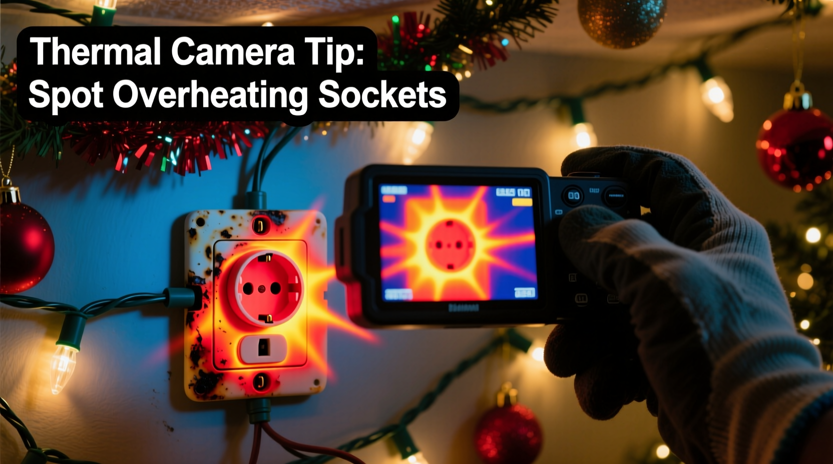
A thermal camera detects infrared radiation emitted by objects and converts it into a visual image based on surface temperature. Warmer areas appear as red, orange, or yellow, while cooler zones show up as purple, blue, or black. These images help users quickly locate hotspots in electrical systems without direct contact.
For holiday lighting inspections, you don't need industrial-grade equipment. Modern handheld thermal cameras and smartphone attachments offer sufficient resolution (as low as 80x60 pixels) and accuracy (±2°C) for residential use. Prices have dropped significantly, with reliable models available under $200.
The key principle: electricity flowing through resistance generates heat. Loose wire nuts, corroded terminals, undersized conductors, or daisy-chained adapters all increase resistance—and thus temperature—at connection points. A properly functioning socket should run only slightly warm. Anything significantly hotter than its surroundings warrants immediate attention.
Step-by-Step Guide: Inspecting Your Holiday Light Circuit
Follow this structured approach to ensure a thorough and safe inspection using your thermal camera.
- Prepare the Environment: Turn off nearby heat sources like space heaters or direct sunlight. Conduct the test indoors, in a dimly lit room, so screen glare doesn’t interfere with readings.
- Power Up the Circuit: Plug in your full string of holiday lights and let them operate for at least 20 minutes. Include any splitters, power strips, or extension cords used in normal operation.
- Set Camera Emissivity: Most consumer thermal cameras default to an emissivity of 0.95, suitable for plastics and painted surfaces common in outlets and sockets. Adjust only if inspecting bare metal components.
- Scan All Connection Points: Slowly move the camera across each outlet, adapter, junction box, and individual socket where bulbs are inserted. Pay close attention to wall outlets powering the circuit and any multi-plug strips.
- Identify Temperature Anomalies: Look for spots more than 10–15°C above ambient temperature or noticeably warmer than adjacent components. Bright yellow or white spots indicate high heat concentration.
- Document Findings: Save thermal images showing hotspots for reference. Note the exact location and associated device (e.g., “outlet near tree base,” “third connector on strand B”).
- Take Corrective Action: Unplug immediately if temperatures exceed 60°C (140°F) or if insulation appears deformed. Replace faulty components before reuse.
This process takes less than 30 minutes but could prevent a catastrophic failure later in the season.
Common Hotspot Locations and What They Mean
Certain parts of a holiday lighting system are more prone to overheating due to design limitations or misuse. Knowing where to look—and why—helps prioritize your inspection.
| Location | Possible Cause | Risk Level |
|---|---|---|
| Wall Outlet Faceplate | Overloaded circuit, loose internal wiring | High – Potential fire inside wall |
| Extension Cord Connector | Damaged prongs, moisture ingress, undersized gauge | Medium-High – Melting risk, short circuit |
| Socket Base (bulb holder) | Corroded contact, incorrect bulb wattage | Medium – Can ignite surrounding materials |
| Power Strip Input Port | Daisy-chaining multiple strips, poor ventilation | High – Common failure point in holiday setups |
| Wire Splice or Junction Box | Inadequate insulation, oxidation | Medium – Hidden hazard behind walls or trim |
Even minor discoloration or warping around a socket suggests prolonged overheating. If detected via thermal scan, assume the component is compromised and replace it.
Real Example: A Prevented Hazard in a Suburban Home
Last December, homeowner Lisa Tran in Portland, Oregon, decided to test her new FLIR ONE Pro thermal camera on her Christmas tree lights after reading about holiday fire risks. She had strung three 50-light incandescent sets together, powered through a six-outlet power strip plugged into a living room outlet.
After running the display for 25 minutes, she scanned the base of the tree. The thermal image revealed a bright yellow hotspot at the female end of the first extension cord—measuring 73°C (163°F)—while other connectors remained below 35°C. The outlet itself showed moderate heating (52°C), but not alarming levels.
Upon unplugging and disassembling the cord, she found one of the copper prongs was partially melted and misaligned, causing uneven current distribution. She replaced the cord and retested: temperatures dropped to a uniform 30–34°C across all connections.
Lisa avoided what could have become a serious incident. Had the faulty cord remained in use overnight or unattended, it might have ignited nearby dry pine needles or carpet fibers.
Checklist: Thermal Inspection of Holiday Lighting Circuits
- ☑ Ensure all lights are plugged in and operating normally before scanning
- ☑ Allow minimum 20 minutes of runtime for thermal stabilization
- ☑ Scan all outlets, cords, splitters, and individual sockets
- ☑ Compare temperatures between similar components (e.g., multiple sockets)
- ☑ Flag any area exceeding 10°C above ambient or visibly brighter than surroundings
- ☑ Document thermal anomalies with photos and notes
- ☑ Replace or repair overheating components immediately
- ☑ Re-scan after repairs to confirm resolution
Best Practices for Safe Holiday Lighting Beyond Thermal Scans
While thermal imaging is powerful, it's only one layer of safety. Combine it with proven electrical practices to minimize risk throughout the season.
Use LED lights whenever possible. They consume up to 90% less energy than incandescent bulbs and produce far less heat. Even if a socket develops resistance, the lower current reduces the chance of dangerous overheating.
Follow manufacturer guidelines on maximum run lengths. Most light strings specify a “maximum number of sets allowed to be connected.” Exceeding this limit overloads the first socket in the chain—the most common failure point.
Plug holiday lights into GFCI-protected outlets, especially outdoors. Ground Fault Circuit Interrupters shut off power during irregular current flow, reducing electrocution and fire risk.
Inspect wires manually before installation. Look for fraying, cracked insulation, or bent plug prongs. Damaged physical condition often correlates with internal faults detectable later via thermal imaging.
“The safest circuit is one designed within limits. No amount of monitoring replaces proper load management.” — Carlos Mendez, Residential Electrician with 22 Years Experience
Frequently Asked Questions
Can I use a non-contact infrared thermometer instead of a thermal camera?
You can, but it’s far less effective. Infrared thermometers measure only a single spot (usually 1–2 inches wide), making it easy to miss small hotspots between sockets or inside outlets. Thermal cameras provide a full-field view, revealing gradients and comparative heat patterns essential for accurate diagnosis.
What temperature is considered dangerous for a light socket?
Sockets running above 60°C (140°F) should be treated as hazardous. Normal operating temperature for a healthy LED or incandescent socket is typically 30–45°C. Temperatures above 70°C indicate severe resistance or overload and require immediate disconnection.
Do I need professional training to interpret thermal images?
No formal certification is needed for basic residential use. However, understanding context is crucial. For example, a warm outlet isn’t automatically faulty—it may simply be handling a heavy but safe load. Focus on relative differences: a single glowing hotspot amid cooler components is far more concerning than uniformly warm equipment.
Conclusion: Stay Festive, Stay Safe
Your holiday lights should illuminate memories—not pose a threat to your home. Using a thermal camera to inspect sockets and connections adds a critical layer of protection that visual checks alone cannot provide. By identifying overheating components early, you eliminate hidden fire risks and extend the life of your decorations.
This season, make thermal inspection part of your decoration routine—right alongside untangling wires and testing bulb sequences. With just a few minutes of proactive effort, you ensure that the only thing glowing brightly is your tree, not an electrical fault behind the wall.


 浙公网安备
33010002000092号
浙公网安备
33010002000092号 浙B2-20120091-4
Comments
No comments yet. Why don't you start the discussion?