
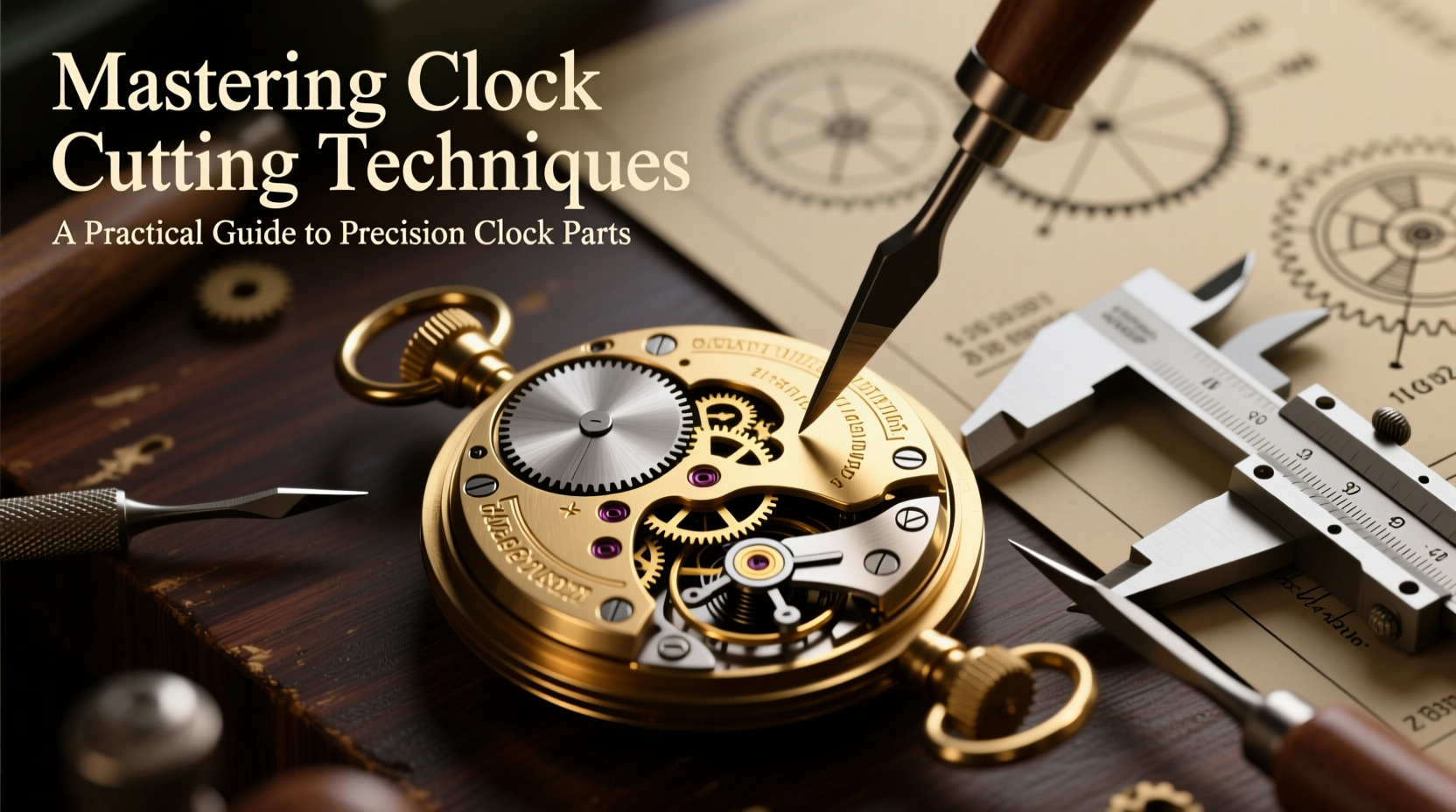
Precision is the soul of horology. Whether restoring an antique timepiece or crafting a new mechanical movement, the accuracy of each gear, pinion, and escapement component determines the reliability and longevity of a clock. At the heart of this precision lies the art of clock cutting—the meticulous shaping and sizing of metal components to exacting tolerances. While modern CNC machines have automated much of this work, traditional hand-cutting methods remain essential for custom builds, restorations, and artisanal craftsmanship. This guide explores proven techniques, tools, and best practices for mastering clock cutting with consistent accuracy.
The Fundamentals of Clock Cutting
Clock cutting involves removing material from brass, steel, or other alloys to produce gears, arbors, pallets, and levers that fit together seamlessly within a movement. Unlike general machining, clockmaking demands tolerances measured in thousandths of an inch (0.001\"). Even minor deviations can lead to excessive wear, poor timekeeping, or complete failure.
The process begins with selecting the right stock material—typically flat brass sheet or round steel rod—followed by precise layout using dividers, rules, and marking tools. From there, cutting is performed via sawing, filing, milling, or broaching, depending on the part’s complexity. The goal is not just dimensional accuracy but also surface finish and geometric symmetry, which influence friction, meshing efficiency, and long-term durability.
Essential Tools for Precision Work
No amount of skill compensates for inadequate tools. A well-equipped clockmaker’s bench includes both measuring instruments and cutting implements calibrated for fine detail work.
| Tool | Primary Use | Recommended Specs |
|---|---|---|
| Dial Calipers | Measuring thickness and diameter | 0.001\" resolution, digital or vernier |
| Dividing Head | Accurate gear tooth spacing | 60:1 ratio with 36-hole plate |
| Precision Files | Fine shaping and deburring | Swiss-pattern, single-cut, needle files |
| Hacksaw or Jeweler’s Saw | Rough cutting blanks | 32 TPI blade for metal |
| Surface Plate & Height Gauge | Layout and alignment checks | Grade A granite, 0.0002\" flatness |
Equally important are fixturing solutions like v-blocks, clamping vises, and tailstock centers that hold parts securely without distortion. Misalignment during cutting introduces runout and eccentricity, undermining even the most careful measurements.
Step-by-Step: Cutting a Custom Spur Gear
Creating a functional spur gear from raw brass demonstrates core principles applicable to many clock components. Follow this sequence for reliable results:
- Select Material: Choose 0.062\" thick brass sheet; anneal if hardened.
- Mark Center: Scribe two perpendicular lines to locate the exact center.
- Drill Arbor Hole: Use a center punch and drill press with a #45 drill bit (0.035\") for the arbor.
- Mount on Dividing Head: Secure blank to an indexing fixture aligned with the milling machine spindle.
- Set Indexing Ratio: For a 12-tooth gear, use 5 holes on a 15-hole dividing plate (4 turns per tooth).
- Cut Teeth: Employ a No. 1 involute cutter on a milling machine, advancing 0.002\" per pass until full depth (~0.040\").
- Deburr and Polish: Use fine abrasive paper and burnishing tool to smooth edges and flanks.
- Test Mesh: Rotate against a known gear to check for binding or backlash.
This method ensures uniform tooth profile and pitch circle alignment—critical for smooth power transmission across the train.
Avoiding Common Mistakes
Even experienced makers fall into traps that compromise part quality. Recognizing these pitfalls early prevents wasted time and materials.
- Skipping Layout Accuracy: Rushing scribing or center-finding leads to off-center cuts and wobble.
- Using Dull Blades: A blunt saw blade drags metal instead of cutting cleanly, distorting the edge.
- Over-tightening Vises: Excessive pressure deforms thin brass discs, causing warping after release.
- Ignoring Backlash: Not accounting for gear train slack results in inconsistent motion transfer.
- Skipping Test Fits: Assembling without dry-fitting parts risks interference and damage during final assembly.
“Precision in clockmaking isn’t about perfection—it’s about consistency. A gear that’s consistently 0.0005\" undersize will perform better than one that varies unpredictably.” — Thomas R. Finch, Master Horologist, American Watchmakers-Clockmakers Institute
Real Example: Restoring a Regulator Clock Escape Wheel
In 2022, a Boston-based restorer faced a challenge when a rare 1890 Ansonia regulator arrived missing its escape wheel. Without original blueprints, replication required reverse engineering. Using calipers and a gear comparator, the maker measured adjacent wheels to infer tooth count (30), module (0.8), and pressure angle (14.5°). A brass disc was cut to 0.780\" diameter, then indexed and milled using a vintage Brown & Sharpe gear cutter. After five test iterations adjusting depth and clearance, the final wheel engaged smoothly with the pallet fork, restoring accurate beat and amplitude. The success hinged on patience, iterative testing, and adherence to traditional cutting standards.
Checklist: Pre-Cutting Preparation
- Material is properly annealed and flat
- All dimensions double-checked with micrometer
- Indexing setup tested with dummy run
- Cutter matches gear module and pressure angle
- Workholding prevents vibration and slippage
- Safety glasses and workshop lighting are adequate
Frequently Asked Questions
Can I cut clock gears by hand without a milling machine?
Yes, though it requires exceptional skill. Hand-cutting involves using a jeweler’s saw to rough out teeth, followed by filing each flank to match an involute template. It’s feasible for low-torque applications but impractical for high-precision or production work.
What’s the ideal surface finish for clock gears?
A smooth, burr-free surface with a matte sheen is optimal. Over-polishing increases friction due to molecular adhesion; light burnishing suffices to remove tool marks while maintaining micro-texture for oil retention.
How do I prevent chatter during milling?
Chatter arises from loose setups or incorrect feed rates. Ensure all components are rigidly secured, use sharp cutters, and maintain spindle speeds between 800–1200 RPM for small-diameter cutters. Lighter, multiple passes outperform aggressive single-depth cuts.
Conclusion: Elevating Craft Through Practice
Mastery in clock cutting doesn’t come from isolated techniques but from disciplined repetition, attention to detail, and respect for the mechanics of time itself. Each gear shaped, each arbor turned, contributes to a legacy of precision that defines fine horology. Whether you’re building your first verge escapement or reproducing a lost crown wheel, the principles remain unchanged: measure twice, cut once, and always prioritize consistency over speed.


 浙公网安备
33010002000092号
浙公网安备
33010002000092号 浙B2-20120091-4
Comments
No comments yet. Why don't you start the discussion?