
Understanding how to solve for current in an electrical circuit is a foundational skill for engineers, technicians, and students alike. Whether you're analyzing a simple flashlight circuit or designing complex power systems, the ability to accurately determine current flow ensures safety, efficiency, and functionality. Current, measured in amperes (A), represents the rate of electron flow through a conductor. Solving for it requires a clear grasp of Ohm’s Law, Kirchhoff’s Laws, and systematic problem-solving strategies. This guide breaks down the process into logical steps, supported by real-world examples and expert insights.
Understanding the Basics: What Is Current?
Electric current is the movement of electric charge through a conductive path. In most cases, this refers to the flow of electrons through wires, resistors, and other components in a closed loop. The direction of conventional current is defined as flowing from positive to negative, opposite to electron flow—a historical convention still used today.
To solve for current, you must first identify the key variables involved:
- Voltage (V): The electrical potential difference that drives current.
- Resistance (R): The opposition to current flow in a material.
- Current (I): The resulting flow of charge, calculated using known values of voltage and resistance.
Step-by-Step Guide to Solve for Current
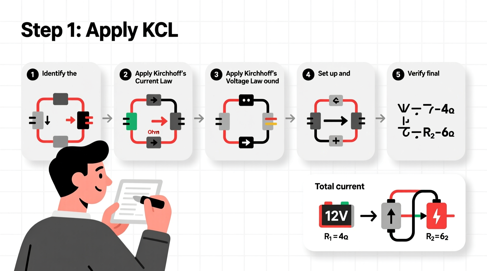
Solving for current isn’t guesswork—it follows a repeatable sequence grounded in physics principles. Follow these six steps to confidently analyze any basic DC circuit.
- Identify the Circuit Type: Determine if the circuit is series, parallel, or a combination. This affects how voltage and resistance are distributed.
- Determine Known Values: Note all given voltages, resistances, and any existing current measurements.
- Simplify the Circuit: Combine resistors where possible using series and parallel formulas:
- Series: \\( R_{total} = R_1 + R_2 + \\dots + R_n \\)
- Parallel: \\( \\frac{1}{R_{total}} = \\frac{1}{R_1} + \\frac{1}{R_2} + \\dots + \\frac{1}{R_n} \\)
- Apply Ohm’s Law: Use \\( I = \\frac{V}{R} \\) once total voltage and equivalent resistance are known.
- Use Kirchhoff’s Laws if Needed:
- Kirchhoff’s Current Law (KCL): Total current entering a junction equals total leaving.
- Kirchhoff’s Voltage Law (KVL): Sum of voltage drops around a closed loop is zero.
- Verify Your Results: Check if currents make sense based on component behavior and power conservation.
Real Example: Solving for Current in a Series Circuit
Consider a 12V battery connected to three resistors in series: 2Ω, 3Ω, and 5Ω.
- Total Resistance: \\( R_{total} = 2 + 3 + 5 = 10\\Omega \\)
- Apply Ohm’s Law: \\( I = \\frac{V}{R} = \\frac{12V}{10\\Omega} = 1.2A \\)
In a series circuit, current remains constant throughout—all components carry 1.2A.
Another Example: Parallel Resistors
A 9V battery powers two parallel resistors: 6Ω and 3Ω.
- Calculate Equivalent Resistance: \\( \\frac{1}{R_{eq}} = \\frac{1}{6} + \\frac{1}{3} = \\frac{1}{6} + \\frac{2}{6} = \\frac{3}{6} = \\frac{1}{2} \\) → \\( R_{eq} = 2\\Omega \\)
- Find Total Current: \\( I = \\frac{9V}{2\\Omega} = 4.5A \\)
- Branch Currents:
- Through 6Ω: \\( I_1 = \\frac{9V}{6\\Omega} = 1.5A \\)
- Through 3Ω: \\( I_2 = \\frac{9V}{3\\Omega} = 3A \\)
Check: \\( 1.5A + 3A = 4.5A \\)—confirms KCL holds true.
Common Pitfalls and How to Avoid Them
Even experienced learners make mistakes when solving for current. Awareness of frequent errors improves accuracy.
| Pitfall | Why It Happens | How to Prevent |
|---|---|---|
| Misidentifying circuit type | Assuming all circuits are series without checking connections | Trace current paths; look for shared nodes indicating parallel branches |
| Incorrect unit conversions | Using mA instead of A or kΩ instead of Ω | Convert all values to base units before calculations |
| Forgetting internal resistance | Ignoring battery or source resistance in advanced problems | Include internal resistance in total R when specified |
| Overlooking open or short circuits | Not recognizing broken paths or zero-resistance faults | Inspect each branch for continuity before analysis |
“Precision in measurement and attention to circuit topology separate competent analysts from those who rely on memorization.” — Dr. Alan Reyes, Electrical Engineering Professor, MIT
Expert Techniques for Complex Circuits
When dealing with mixed (series-parallel) or multi-loop circuits, structured approaches like mesh analysis or nodal analysis become essential.
Mesh Analysis Method
This technique applies Kirchhoff’s Voltage Law to each independent loop.
- Assign loop currents (e.g., I₁, I₂).
- Write KVL equations for each loop.
- Solve the system of equations simultaneously.
Nodal Analysis Overview
Focuses on voltages at circuit nodes using Kirchhoff’s Current Law.
- Select a reference node (usually ground).
- Define unknown node voltages.
- Apply KCL at each non-reference node.
- Solve for voltages, then compute currents via Ohm’s Law.
Mini Case Study: Troubleshooting a Home Lighting Circuit
A homeowner reports that two ceiling lights in the hallway flicker and dim over time. An electrician investigates.
The circuit uses a 120V supply with two 60W bulbs wired in parallel. Each bulb has a resistance of approximately 240Ω when operating.
Calculations:
- Current per bulb: \\( I = \\frac{P}{V} = \\frac{60W}{120V} = 0.5A \\)
- Total current: \\( 0.5A + 0.5A = 1.0A \\)
After cleaning contacts and replacing damaged wire, both lights operate normally. The issue was not with current demand but with unintended resistance reducing effective voltage delivery—highlighting why theoretical knowledge must be paired with practical diagnostics.
Frequently Asked Questions
Can current be negative?
Yes, in circuit analysis, a negative current indicates that the actual flow is opposite to the assumed direction. It doesn’t mean “less than zero” physically, just reversed relative to your initial guess.
What if there’s no resistor in the circuit?
A circuit with no resistance implies a short circuit. In theory, current would approach infinity (\\( I = V/0 \\)), which is dangerous. Real circuits always have some resistance—even wires contribute small amounts.
How do capacitors and inductors affect current?
In DC steady state, capacitors block current after charging, while inductors act as short circuits. In AC circuits, they introduce reactance, requiring impedance-based calculations (\\( I = V/Z \\)).
Conclusion and Call to Action
Mastering how to solve for current step by step transforms abstract concepts into actionable engineering skills. From applying Ohm’s Law in simple setups to using Kirchhoff’s rules in intricate networks, each method builds confidence and precision. Remember: clarity in setup, consistency in units, and verification of results are the pillars of reliable circuit analysis.
Now that you’ve seen practical frameworks and real applications, try solving a new circuit today—start with a flashlight design or a household outlet setup. Practice strengthens intuition. Share your solutions, ask questions, and engage with others learning the same principles.


 浙公网安备
33010002000092号
浙公网安备
33010002000092号 浙B2-20120091-4
Comments
No comments yet. Why don't you start the discussion?