
Precision is non-negotiable in machining, manufacturing, and quality control. A small deviation in measurement can lead to part failure, safety risks, or costly rework. Among the most trusted tools for detecting minute dimensional changes is the dial gauge—also known as a dial indicator. But even the finest instrument loses its value if not properly calibrated. Calibration ensures that your readings reflect true physical dimensions, not just relative movement. This guide walks you through the essential steps, best practices, and common pitfalls of calibrating a dial gauge to maintain measurement integrity across applications.
Why Calibration Matters
Dial gauges measure linear displacement with high sensitivity—often down to 0.001 inches (0.025 mm) or finer. Over time, wear, shock, temperature fluctuations, or improper handling can shift internal components, leading to inaccurate readings. An uncalibrated gauge may show zero when it shouldn’t, or fail to register actual movement due to hysteresis or gear backlash.
Regular calibration isn't just about compliance; it's about confidence. When engineers, machinists, or inspectors trust their instruments, they make better decisions. In regulated industries like aerospace or medical device manufacturing, traceable calibration is often required by ISO standards such as ISO 9001 or AS9100.
“Measurement uncertainty begins where calibration ends. If your dial gauge isn’t verified against a known standard, you’re measuring guesswork.” — Dr. Alan Reeves, Metrology Lab Director at Precision Instruments Group
Essential Tools and Environment for Calibration
Before beginning calibration, gather the necessary equipment and prepare a stable environment. Accuracy depends on consistency—not only in procedure but also in conditions.
- Grade 0 or Grade 1 Gage Blocks: These are precision-ground blocks used as reference standards. They come in sets with certified dimensions traceable to national laboratories.
- Surface Plate: A flat granite or cast iron plate providing a stable, level reference surface.
- Magnetic Stand with Holder: Securely holds the dial gauge perpendicular to the surface plate.
- Deburring Tool or Soft Cloth: For cleaning gage blocks and contact points.
- Temperature-Stable Room: Ideal calibration occurs at 20°C (68°F), minimizing thermal expansion effects.
- Feeler Gauge (optional): Useful for verifying small displacements during functional checks.
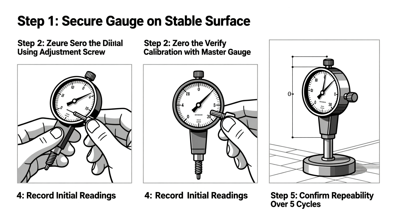
Step-by-Step Calibration Procedure
Follow this systematic process to ensure reliable calibration results. Perform these steps before each critical use or at scheduled intervals based on usage frequency.
- Prepare the Workspace: Clean the surface plate and all tools. Ensure no vibrations or drafts affect the setup. Allow the dial gauge and gage blocks to acclimate to room temperature for at least two hours.
- Mount the Dial Gauge: Attach the gauge securely to the magnetic stand. Position it so the plunger moves perpendicularly to the surface plate. Misalignment introduces cosine error, skewing readings.
- Zero the Indicator: Lower the plunger until it makes light contact with the surface plate. Rotate the outer bezel to align the needle with zero. Do not rely on factory-set zeros—always re-zero in situ.
- Select Reference Gage Blocks: Choose blocks that represent common measurement ranges you’ll use. Stack them carefully using wringing technique (sliding surfaces together under light pressure to create molecular adhesion).
- Apply Known Displacement: Place the stacked blocks under the plunger tip. Raise the gauge slightly, then lower it gently onto the blocks. Record the reading.
- Compare and Adjust: If the dial shows a deviation (e.g., reads 0.003\" when block stack is exactly 0.100\"), note the error. Some gauges allow internal adjustment via screw mechanisms; others require sending to a metrology lab.
- Test Multiple Points: Repeat across various increments—e.g., 0.025\", 0.050\", 0.100\"—to check linearity. Backlash should be tested by lifting and re-engaging the plunger at the same point.
- Document Results: Record observed values, environmental conditions, and any adjustments made. Keep logs for audit trails and trend analysis.
Common Errors and How to Avoid Them
Even experienced technicians can fall into traps that compromise calibration accuracy. Awareness is the first defense.
| Common Error | Impact | Prevention Strategy |
|---|---|---|
| Improper Plunger Alignment | Cosine error inflates readings | Use a square or alignment jig to verify 90° angle |
| Dirty or Worn Contact Tip | Reduced sensitivity, false zero | Inspect tip regularly; replace if pitted or flattened |
| Thermal Drift | Expansion/contraction alters dimensions | Allow thermal stabilization; avoid direct sunlight |
| Over-Tightening Mount | Distorts gauge housing, affects mechanics | Tighten just enough to prevent movement |
| Using Uncertified Standards | Invalidates entire calibration chain | Only use traceable, recently certified gage blocks |
Mini Case Study: Calibration Failure in Automotive Production
In 2022, a Tier-1 automotive supplier began receiving complaints about brake rotor thickness variation. Internal audits revealed that several dial gauges used in final inspection had not been recalibrated after a facility move. One gauge showed consistent 0.002-inch low readings due to misaligned mounting. As a result, over 1,200 rotors passed inspection despite being out of tolerance. The company initiated a full recalibration protocol, implemented monthly verification checks, and introduced color-coded tags indicating last calibration date. Defect rates dropped by 94% within six weeks.
This case underscores how seemingly minor calibration lapses can cascade into major quality issues. Proactive maintenance prevents reactive crises.
Calibration Checklist
Use this checklist before every calibration session to ensure completeness and consistency:
- ☐ Work area clean and free of vibration
- ☐ Surface plate leveled and undamaged
- ☐ Dial gauge securely mounted without stress
- ☐ Plunger moves freely without binding
- ☐ Gage blocks cleaned and wrung properly
- ☐ Temperature stabilized (within ±1°C of nominal)
- ☐ Zero set against reference surface
- ☐ Readings recorded at multiple test points
- ☐ Backlash checked by repeated engagement
- ☐ Results documented with operator name and date
Frequently Asked Questions
How often should I calibrate my dial gauge?
For general workshop use, monthly calibration is recommended. In high-precision or production environments, weekly or per-shift checks are advisable. Also recalibrate after any impact, disassembly, or long-term storage.
Can I calibrate a dial gauge without gage blocks?
While makeshift methods exist (e.g., using micrometers or feeler gauges), they lack the traceability and accuracy required for true calibration. For reliable results, always use certified gage blocks on a surface plate.
What does “parallax error” mean when reading a dial gauge?
Parallax error occurs when viewing the dial from an angle, causing the needle to appear off-scale. Always read the gauge directly from the front, ensuring your eye is perpendicular to the face.
Conclusion: Build Precision Into Every Measurement
Calibrating a dial gauge isn’t a one-time setup—it’s an ongoing discipline. Each step, from environmental control to documentation, contributes to the reliability of your measurements. Whether you're inspecting engine components, aligning shafts, or verifying tolerances in CNC parts, precision starts with a properly calibrated tool in skilled hands.


 浙公网安备
33010002000092号
浙公网安备
33010002000092号 浙B2-20120091-4
Comments
No comments yet. Why don't you start the discussion?