
The specialized air tool switch comp pump is a critical component in modern pneumatic systems, widely used across automotive workshops, manufacturing facilities, and industrial maintenance environments. Unlike standard compressors, these units integrate intelligent switching mechanisms that regulate airflow dynamically based on demand, improving energy efficiency and tool responsiveness. Yet, despite their advanced design, many operators underutilize or mismanage these systems due to incomplete understanding of their operation, maintenance, and optimization strategies. This guide provides a comprehensive walkthrough of how to master your switch comp pump for peak performance, longevity, and operational safety.
Understanding the Switch Comp Pump: How It Works
A switch comp pump—short for “switch-controlled compressor pump”—is engineered to deliver compressed air only when needed. It uses pressure sensors and electronic switches to activate or deactivate the motor, eliminating constant running and reducing wear. When an air tool engages, pressure drops trigger the switch to restart the compressor. Once the system reaches the set pressure threshold, it shuts off automatically.
This on-demand functionality distinguishes it from traditional reciprocating compressors that run continuously or cycle frequently without load sensing. The result is reduced energy consumption, lower noise levels, and minimized heat buildup—all contributing to longer component life.
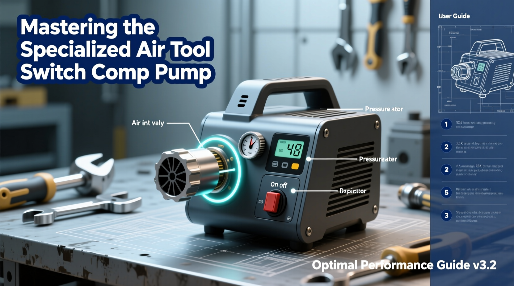
Key components include:
- Pressure transducer: Monitors system pressure in real time.
- Electronic control module: Processes sensor data and manages motor activation.
- Automatic drain valve: Prevents moisture accumulation in the tank.
- Thermal overload protector: Safeguards against overheating.
- Regulator and filter assembly: Ensures clean, consistent airflow to tools.
Optimizing Performance Through Proper Setup
Proper installation is foundational to reliable operation. Even high-end equipment underperforms if not configured correctly. Begin by selecting a stable, well-ventilated location away from dust, moisture, and extreme temperatures. Mount the unit securely to prevent vibration-related damage.
Connect the power supply according to manufacturer specifications. Most switch comp pumps require 110V or 220V dedicated circuits with adequate amperage. Undersized wiring leads to voltage drop, causing slow recovery times and premature motor failure.
Plumb the air delivery system using reinforced rubber or braided nylon hoses rated for your maximum operating pressure (typically 150 PSI). Avoid sharp bends or kinks, which restrict airflow and create backpressure. Use Teflon tape on all threaded connections to prevent leaks.
“An improperly installed switch comp pump can waste up to 30% more energy than a properly configured one.” — Carlos Mendez, Industrial Pneumatics Engineer, FluidAir Dynamics
Step-by-Step Startup Procedure
- Inspect all fittings and hoses for damage or looseness.
- Open the drain valve briefly to purge any residual moisture.
- Close the valve and ensure the pressure regulator is set to zero.
- Power on the unit and allow it to reach full cut-out pressure (usually 120–130 PSI).
- Gradually adjust the regulator to match your tool’s recommended PSI.
- Test airflow with a connected tool; listen for irregular cycling or hissing.
Maintenance Checklist for Long-Term Reliability
Preventive maintenance extends service life and avoids costly downtime. Follow this monthly checklist to keep your switch comp pump operating efficiently:
- Drain moisture from the tank after each use.
- Inspect air filters for clogging; replace every 3 months.
- Check belts (if applicable) for tension and wear.
- Verify electrical connections are tight and corrosion-free.
- Test pressure switch response with a calibrated gauge.
- Lubricate moving parts as specified in the manual.
- Clean cooling fins and intake vents with dry compressed air.
Every six months, perform a deeper inspection: disassemble and clean the intake valve, examine piston rings (in oil-lubricated models), and test the thermal cutoff switch. Keep a log of all maintenance activities to track patterns and anticipate part replacements.
Common Issues and Troubleshooting Table
Even well-maintained systems encounter problems. Use the table below to diagnose frequent issues quickly.
| Issue | Possible Cause | Solution |
|---|---|---|
| Unit fails to start | Tripped breaker, blown fuse, low voltage | Reset breaker, check fuse, verify input voltage |
| Short cycling (frequent on/off) | Leak in system, faulty pressure switch, oversized tool demand | Inspect for leaks, recalibrate switch, match tool CFM to output |
| Low air pressure | Clogged filter, worn pump seals, undersized hose | Replace filter, inspect pump, upgrade hose diameter |
| Excessive noise | Loose mounting, failing bearings, trapped air in lines | Re-tighten bolts, lubricate or replace bearings, bleed lines |
| Motor overheats | Poor ventilation, continuous duty beyond rating, voltage fluctuation | Improve airflow, reduce runtime, install voltage stabilizer |
Real-World Example: Auto Body Shop Efficiency Upgrade
An auto repair facility in Denver struggled with inconsistent spray gun performance and frequent compressor shutdowns. Their 5 HP switch comp pump was cycling every 90 seconds during sanding operations, leading to downtime and poor finish quality. A site audit revealed two root causes: a cracked airline joint leaking 18 CFM and an undersized air receiver tank unable to buffer sudden demand spikes.
The team replaced the damaged hose section, installed a 60-gallon auxiliary tank, and recalibrated the pressure switch differential from 20 PSI to 35 PSI. Post-adjustment, cycle frequency dropped to once every 4 minutes, energy consumption decreased by 22%, and painters reported smoother airflow. This case underscores how proper tuning and system balancing directly impact productivity.
Maximizing Energy Efficiency and Tool Compatibility
To extract optimal value from your switch comp pump, align its capabilities with your toolset. Each pneumatic device has a specific CFM (cubic feet per minute) requirement at a given PSI. Exceeding the pump’s sustained CFM output causes pressure droop and inefficient operation.
For example, a 1/2” impact wrench typically requires 5–7 CFM at 90 PSI, while a dual-action sander may need 10–12 CFM. If your switch comp pump delivers only 8 CFM max, running both tools simultaneously will overwhelm the system. Plan your workflow accordingly or upgrade to a higher-capacity model.
Additionally, consider installing a centralized filtration system with coalescing filters to remove oil aerosols and particulates. Clean air protects both your tools and the internal components of the pump, especially in environments with high dust or humidity.
Frequently Asked Questions
Can I leave my switch comp pump running unattended?
Yes, provided it has built-in safety features like thermal overload protection, automatic shut-off, and a functioning pressure relief valve. However, never leave it running overnight or during non-operational hours to minimize fire risk and energy waste.
Why does my pump take longer to recharge after heavy use?
Extended recovery times often indicate overheating, restricted intake airflow, or moisture buildup in the tank. Allow the unit to cool for 15–20 minutes, clean the intake filter, and drain the tank. Persistent delays may signal worn valves or piston rings requiring service.
Is it safe to use an extension cord with my switch comp pump?
Only if the cord is heavy-duty (12-gauge or thicker), as short as possible, and rated for the pump’s amperage. Voltage drop from undersized cords reduces motor torque and increases heat, potentially damaging windings. Direct wall outlet connection is always preferred.
Conclusion: Take Control of Your Air System
Mastering the specialized air tool switch comp pump isn’t just about fixing problems—it’s about creating a responsive, efficient, and durable pneumatic ecosystem. From precise setup and routine care to diagnosing subtle performance hiccups, every action contributes to smoother workflows and reduced operating costs. Whether you're powering a single impact gun or managing a multi-station garage, treating your compressor as a high-performance asset pays dividends in reliability and results.


 浙公网安备
33010002000092号
浙公网安备
33010002000092号 浙B2-20120091-4
Comments
No comments yet. Why don't you start the discussion?