
Understanding how to calculate total current in an electrical circuit is foundational for engineers, technicians, and hobbyists alike. Whether you're designing a simple flashlight circuit or analyzing a complex power distribution network, knowing how current behaves across different configurations ensures accuracy, safety, and efficiency. This guide walks through the principles, methods, and practical applications of total current calculation, equipping you with the tools needed for confident circuit analysis.
Understanding Current and Its Role in Circuits
Electric current, measured in amperes (A), represents the flow of electric charge through a conductor. In direct current (DC) circuits, this flow is unidirectional; in alternating current (AC), it periodically reverses direction. The total current in a circuit depends on voltage sources and the overall resistance—or impedance in AC—offered by components such as resistors, capacitors, and inductors.
Total current is not just a theoretical value—it determines wire sizing, fuse selection, component ratings, and system performance. Misjudging current can lead to overheating, equipment failure, or even fire hazards. Therefore, precise calculation is essential.
“Accurate current analysis prevents design flaws before they become costly failures.” — Dr. Alan Reyes, Electrical Systems Engineer
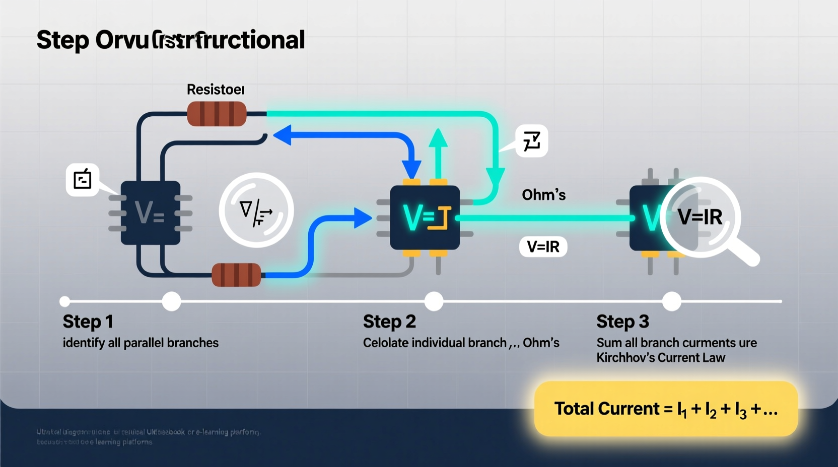
Step-by-Step Guide to Calculating Total Current
The process of calculating total current varies depending on whether the circuit is series, parallel, or a combination. Follow these steps systematically to ensure correctness:
- Identify the Circuit Type: Determine if components are connected in series, parallel, or a mix. This affects how resistance and current are calculated.
- Determine the Total Voltage: Locate all voltage sources. In most basic DC circuits, there's a single source like a battery.
- Calculate Equivalent Resistance: Use series and parallel resistance formulas to simplify the circuit into a single equivalent resistor.
- Apply Ohm’s Law: Use the formula I = V/R, where I is total current, V is total voltage, and R is equivalent resistance.
- Verify Using Kirchhoff’s Laws: Confirm your result using Kirchhoff’s Current Law (KCL) at junctions and Kirchhoff’s Voltage Law (KVL) around loops.
Series Circuits: One Path for Current
In a series circuit, components share a single path. The same current flows through each element. Total resistance is the sum of individual resistances:
R_total = R₁ + R₂ + R₃ + ...
Once R_total is known, apply Ohm’s Law:
I_total = V_source / R_total
For example, a 12V battery connected to three resistors (2Ω, 3Ω, and 5Ω) in series yields:
R_total = 2 + 3 + 5 = 10Ω
I_total = 12V / 10Ω = 1.2A
Parallel Circuits: Multiple Current Paths
In parallel circuits, voltage across each branch is the same, but current divides among branches. Total resistance is found using:
1/R_total = 1/R₁ + 1/R₂ + 1/R₃ + ...
Then, I_total = V_source / R_total
Example: A 9V battery powers two parallel resistors: 6Ω and 3Ω.
1/R_total = 1/6 + 1/3 = 1/6 + 2/6 = 3/6 = 1/2 → R_total = 2Ω
I_total = 9V / 2Ω = 4.5A
Branch currents can be verified: I₁ = 9V/6Ω = 1.5A, I₂ = 9V/3Ω = 3A. Sum: 1.5 + 3 = 4.5A, matching total.
Kirchhoff’s Laws: The Foundation of Complex Analysis
For mixed or complex networks, Ohm’s Law alone isn’t sufficient. Gustav Kirchhoff’s two laws provide a robust framework:
- Kirchhoff’s Current Law (KCL): The sum of currents entering a junction equals the sum leaving it. Charge is conserved.
- Kirchhoff’s Voltage Law (KVL): The sum of potential differences around any closed loop is zero. Energy is conserved.
These laws allow systematic node and mesh analysis, especially useful in circuits with multiple loops or sources.
Mini Case Study: Troubleshooting a Lighting Circuit
A technician is called to diagnose a dim lighting system in a recreational vehicle. The 12V system uses four LED lights wired in parallel. Each light draws 0.5A under normal conditions, so expected total current is 2.0A. However, the ammeter reads only 1.2A.
Using KCL, the technician checks each branch. Three lights draw 0.5A each (1.5A total), but one draws only 0.1A. Further inspection reveals a corroded connector increasing resistance in that branch. After cleaning the connection, current returns to 0.5A per light, restoring full brightness and confirming the initial calculation.
This case illustrates how understanding total current helps identify faults and validate repairs.
Common Pitfalls and Best Practices
Even experienced analysts make mistakes when calculating current. Below is a checklist to avoid common errors:
- ✅ Double-check circuit topology before simplifying.
- ✅ Label all nodes, currents, and voltage polarities clearly.
- ✅ Use consistent units (e.g., volts, ohms, amps—avoid mixing mA and A).
- ✅ Verify calculations with both Ohm’s Law and Kirchhoff’s Laws.
- ✅ Simulate if possible using software like SPICE for validation.
| Do | Don't |
|---|---|
| Redraw complex circuits for clarity | Assume configuration without verifying connections |
| Use subscripts for branch currents (I₁, I₂) | Mix up series and parallel resistance formulas |
| Start with known values (voltage sources) | Ignore internal resistance of batteries or sources |
| Check if results are physically reasonable (e.g., no negative resistance) | Forget to ground reference points in multi-loop circuits |
Frequently Asked Questions
Can total current exceed the source’s rated output?
No. If a circuit demands more current than the source can supply, the voltage will drop, components may overheat, or the source could fail. Always ensure the power supply matches or exceeds the calculated load requirements.
How does temperature affect current calculations?
Resistance in conductors increases with temperature. For precision work, especially in high-power systems, use temperature coefficients to adjust resistance values before calculating current. Ignoring thermal effects can lead to underestimated current and unsafe designs.
Is total current the same in AC and DC circuits?
The concept is similar, but AC introduces impedance (resistance + reactance from capacitors and inductors). In AC, use I = V/Z, where Z is impedance. Phase angles also matter in vector calculations.
Advanced Insight: Superposition in Multi-Source Circuits
When a circuit contains multiple independent sources (e.g., two batteries), the superposition theorem allows you to analyze the effect of each source individually. To apply it:
- Turn off all but one source (replace voltage sources with short circuits, current sources with open circuits).
- Calculate the current contribution from the active source.
- Repeat for each source.
- Sum all contributions algebraically to find total current.
This method is invaluable in analyzing circuits with overlapping influences, though it applies only to linear systems.
Conclusion: Build Confidence Through Practice
Mastering total current calculation is not about memorizing formulas—it’s about developing a structured approach to circuit analysis. By combining Ohm’s Law, Kirchhoff’s Laws, and systematic problem-solving techniques, you gain the ability to tackle increasingly complex systems with confidence. Start with simple circuits, verify each step, and gradually build up to real-world applications in electronics, automotive systems, or renewable energy setups.


 浙公网安备
33010002000092号
浙公网安备
33010002000092号 浙B2-20120091-4
Comments
No comments yet. Why don't you start the discussion?