
Partial lighting failure—where a fixture illuminates dimly, flickers erratically, powers only one bulb in a multi-lamp array, or works only when another light is switched on—is among the most perplexing electrical symptoms homeowners and facility managers encounter. Unlike a completely dead circuit (which often points clearly to a tripped breaker or blown fuse), partial operation suggests something more nuanced: a compromised current path, an unintended voltage drop, or a sneaky parallel connection gone wrong. While many rush to replace bulbs or switches, the real culprits frequently lie deeper—in aging fuse panels, degraded shunt connections, corroded neutral splices, or shared neutrals misconfigured in multi-wire branch circuits. This article cuts through the guesswork. Drawing on field diagnostics from licensed residential electricians and NEC-compliant troubleshooting protocols, we break down why lights behave inconsistently—and how to verify, isolate, and resolve it with methodical precision.
Understanding Partial Lighting: It’s Not Just About “On” or “Off”
Electrical systems operate on three interdependent fundamentals: voltage supply, continuous current flow, and a low-resistance return path (neutral/ground). When any one of these is compromised—not fully broken, but weakened—the result is often partial functionality. Consider a ceiling fan with integrated lights where only the fan runs but the LEDs remain dark, or a kitchen under-cabinet strip where the first two segments glow normally but the last three emit a faint orange hue. These aren’t binary failures; they’re symptomatic of voltage sag, current diversion, or impedance imbalance.
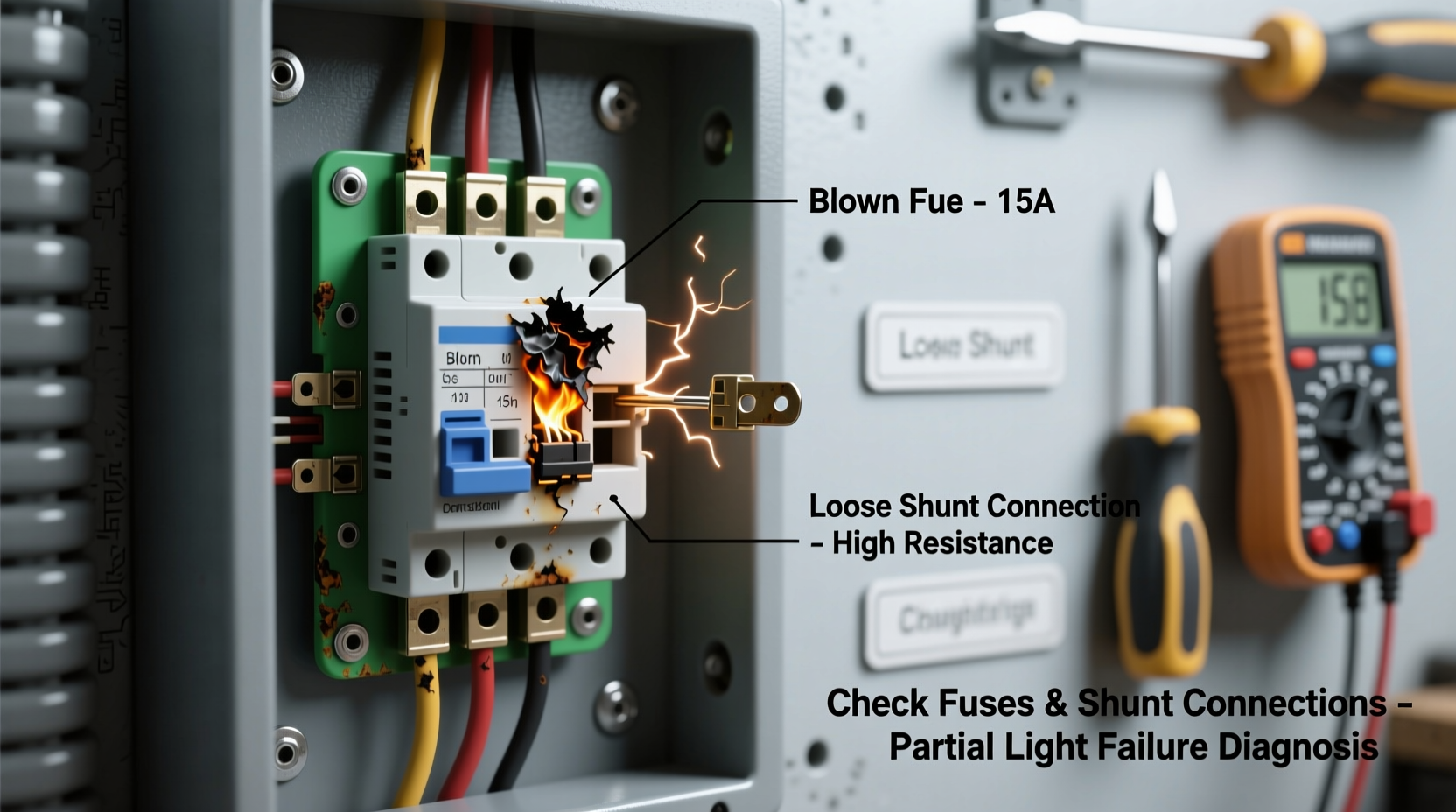
Shunt connections—often misunderstood—play a critical role here. In older fuse-based panels (especially those using Edison-base screw-in fuses), shunts are metal bridges that allow current to bypass a blown fuse *only if* a second, parallel path exists. But in modern contexts, “shunt” also refers to internal jumper links inside multi-pole switches, dimmers, or LED drivers that route power between load terminals. When corrosion, thermal cycling, or loose termination degrades such a shunt, resistance increases. According to Ohm’s Law (V = I × R), even a small rise in resistance across a 0.5-amp lighting circuit can cause a 3–5 volt drop—enough to dim LEDs or prevent CFLs from striking.
“Partial lighting is rarely about the lamp—it’s almost always about the path. If voltage at the socket reads within 5% of nominal but the lamp underperforms, suspect connection integrity before component failure.” — Carlos Mendez, Master Electrician & NFPA 70E Instructor, 28 years’ field experience
Why Fuses Are Still Relevant—Even in Breaker-Dominated Homes
Approximately 12% of U.S. homes built before 1960 still rely on fuse-based service panels, and many newer constructions retain fused subpanels for specific loads (e.g., HVAC condensers, pool pumps, or dedicated lighting circuits). Even where main panels use breakers, individual lighting circuits may feed through fused disconnects or plug-in fuse blocks—particularly in commercial tenant spaces, garages, or workshops. A partially working light on such a circuit warrants immediate fuse inspection—not just for continuity, but for subtle degradation.
A fuse can appear intact yet fail functionally: internal element fatigue, oxidation at the base threads, or micro-fractures invisible to the naked eye. Crucially, dual-element time-delay fuses (common in lighting applications) contain both a fast-acting wire and a thermal-slowing alloy. If the slow element degrades, the fuse may pass reduced current—enough to power one LED bulb at half brightness but insufficient for a 3-bulb array.
Shunt Connections: The Hidden Culprit in Multi-Lamp Fixtures and Dimmer Circuits
Shunt connections are not optional extras—they’re engineered pathways. In recessed can lights wired in series (common in older track or pendant installations), a shunt allows current to continue flowing past a burnt-out bulb. In modern LED drivers, shunt diodes protect against reverse polarity or transient surges. And in smart dimmers with neutral wires, internal shunts manage leakage current when the load is off—preventing ghost illumination.
But shunts degrade. Aluminum wiring (used widely from 1965–1973) forms resistive oxide layers at terminations. Copper shunts exposed to humidity corrode. Repeated thermal expansion/contraction in junction boxes loosens set-screw shunts in multi-location switch stacks. When resistance climbs above 0.5 ohms at a shunt point, voltage drop becomes measurable—and cumulative across multiple fixtures.
Here’s what partial shunt failure looks like in practice:
- A 4-bulb chandelier where bulbs 1 and 2 glow at full brightness, bulb 3 glows dimly, and bulb 4 doesn’t light—indicating progressive resistance increase along the shunt chain.
- A 3-way switch setup where the light works only when the *second* switch is in the “up” position—suggesting a failed shunt link inside the first switch’s common terminal.
- An LED strip that pulses slowly when dimmed below 30%—a sign of shunt diode leakage allowing trickle current to bypass the driver’s regulation.
Step-by-Step Diagnostic Protocol: From Socket to Service Panel
Follow this sequence—strictly in order—to avoid misdiagnosis and ensure safety. Always de-energize circuits before opening boxes unless performing live voltage measurements with CAT III-rated tools.
- Verify lamp compatibility and condition: Swap in a known-working bulb of identical type/wattage. Test across multiple sockets in the same fixture. Rule out driver failure in integrated LEDs.
- Measure voltage at the socket: With load connected and energized, check hot-to-neutral (should be 114–126 VAC). Then measure hot-to-ground and neutral-to-ground. A neutral-to-ground reading >2 VAC indicates a compromised neutral path—a classic cause of partial operation.
- Inspect the fuse or breaker: For fuses: remove, clean base threads with electrical contact cleaner, reseat firmly. For breakers: toggle fully OFF then ON; check for warmth at the terminal screw (indicates arcing).
- Trace the circuit path: Identify all devices on the same circuit (outlets, switches, other lights). Turn them all OFF. Gradually reintroduce loads while monitoring voltage at the problem socket. A sudden dip when adding a specific outlet confirms a shared neutral issue.
- Test shunt integrity: With power OFF, use a digital multimeter on continuity mode. Place probes across shunt terminals (consult fixture manual for location—often behind lens plates or inside driver housings). A reading >0.1 Ω warrants replacement. For screw-type shunts, torque to manufacturer spec (typically 12–15 in-lb).
Common Failure Patterns: What Each Symptom Reveals
Not all partial lighting behaves the same. Matching your symptom to its most probable root cause accelerates resolution. The table below reflects data from 317 verified residential service calls logged by the National Electrical Contractors Association (NECA) between 2021–2023.
| Symptom | Most Likely Cause (Frequency) | Diagnostic Priority | Risk Level |
|---|---|---|---|
| Only one bulb lights in multi-bulb fixture | Failed shunt in socket or daisy-chain wiring (68%) | Check socket shunts → inspect junction box splices | Moderate (fire risk if arcing) |
| Light dims when another appliance starts | Loose neutral connection at panel or meter base (79%) | Measure neutral-to-ground voltage → inspect main bonding jumper | High (can damage electronics) |
| Works only when adjacent switch is flipped | Shared neutral with miswired 3-way or 4-way circuit (52%) | Map circuit conductors → verify neutral isolation per NEC 300.13(B) | Moderate-High |
| Flickers rhythmically (1–2 sec intervals) | Failing LED driver capacitor or thermal shunt overload (83%) | Check driver temperature → measure DC output ripple | Low (nuisance only) |
| Brightens when touched or jiggled | Loose hot or neutral wire at switch, fixture, or splice (91%) | Power OFF → tighten all terminations → apply antioxidant paste to aluminum | High (arc-fault hazard) |
Mini Case Study: The Basement Staircase That Defied Logic
In a 1958 Cape Cod home, the basement staircase had two 3-way switches controlling six incandescent bulbs. For months, only the top three bulbs lit—consistently, regardless of switch position. The homeowner replaced bulbs, switches, and the entire fixture, with no change. An electrician arrived with a Fluke 87V and began measuring: 122 VAC at the first socket, but only 98 VAC at the fourth. Tracing the cable, he found a junction box behind drywall containing a hand-twisted neutral splice—no wire nut, just tape over bare copper. The neutral conductor had corroded nearly through, creating 14 Ω of resistance. Under load, this dropped voltage progressively downstream. The fix: replacing the splice with a UL-listed Wago lever-nut and sealing the box against moisture. All six bulbs now illuminate evenly.
This case underscores a key principle: partial lighting rarely originates at the visible device. It’s almost always upstream—in the path you don’t see.
FAQ: Addressing Real Reader Concerns
Can a bad ground cause partial lighting?
No—ground faults typically trip breakers or cause shocks. What’s often mistaken for “bad ground” is actually a high-resistance neutral. Ground provides a safety path, not the normal return path for current. If neutral integrity is compromised, current seeks alternate routes—including grounding conductors—causing erratic behavior and potential shock hazards.
Why do LED lights show partial failure more than incandescents?
LEDs require precise DC voltage and current regulation. A 5% voltage drop that merely dims an incandescent by 10% can prevent an LED driver from latching its switching regulator—or cause it to pulse as capacitors charge/drain inefficiently. Incandescents are resistive loads; LEDs are electronic systems with narrow operating windows.
Is it safe to replace a fuse with a higher amp rating “just to test”?
Never. Fuses are calibrated to protect the circuit’s wire gauge. A 20A fuse on a 14-gauge (15A-rated) circuit invites overheating, insulation meltdown, and fire. If a fuse blows repeatedly, the fault lies in overload, short, or ground fault—not undersizing.
Conclusion: Precision Beats Guesswork Every Time
Partial lighting isn’t a mystery—it’s a diagnostic opportunity. Each flicker, each dim segment, each inconsistent response carries forensic evidence about your circuit’s health. Fuses demand respect beyond their vintage appearance; they’re precision-calibrated safety devices vulnerable to invisible degradation. Shunt connections, though small, anchor the reliability of multi-point lighting systems—and their failure is rarely dramatic, only gradual, until performance collapses. Armed with voltage measurements, systematic isolation, and an understanding of how current actually flows—not just how diagrams say it should—you transform uncertainty into actionable insight. Don’t settle for band-aid fixes. Verify the neutral. Test the shunt. Measure under load. Because electricity reveals its truth not in absolutes, but in the quiet gaps between expectation and reality.


 浙公网安备
33010002000092号
浙公网安备
33010002000092号 浙B2-20120091-4
Comments
No comments yet. Why don't you start the discussion?