
LED light strips offer flexibility, energy efficiency, and ambiance control unmatched by traditional lighting. But when a portion of your carefully installed strip refuses to illuminate—especially if the rest works perfectly—it can be frustrating and confusing. The issue often lies not in the power supply or controller, but in localized circuit breaks within the strip itself. Understanding why this happens, how to identify it, and what you can do about it is essential for both DIY enthusiasts and professional installers.
Circuit breaks in LED strips are more common than many realize. They result from physical damage, poor soldering, voltage drop, or manufacturing defects. Unlike a complete failure, where no lights turn on, a partial blackout suggests an interruption in continuity along the conductive path. This guide walks through the causes, diagnostic methods, and solutions to restore full illumination.
Understanding LED Strip Circuitry
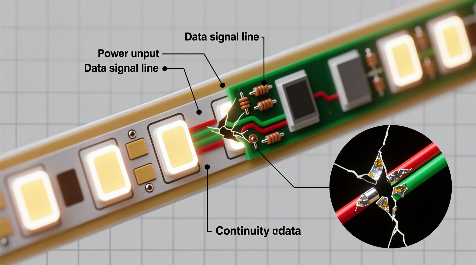
Most flexible LED strips consist of repeating segments of LEDs connected in parallel across copper traces that run the length of the strip. Each segment typically includes three LEDs and a current-limiting resistor, powered by 12V or 24V DC. These segments are electrically isolated at regular intervals (often every 3 or 6 inches), allowing the strip to be cut only at designated points without damaging the circuit.
When a break occurs between these segments—whether due to a severed trace, failed solder joint, or water ingress—the downstream LEDs lose power. Since there’s no redundancy in most standard strips, any discontinuity halts current flow beyond that point. This explains why one end glows while the other remains dark: the circuit is broken somewhere upstream of the dark section.
Voltage drop can also mimic a circuit break. Over long runs, resistance in the copper traces reduces available voltage, causing LEDs at the far end to dim or fail to light. However, true circuit breaks involve a total loss of continuity, which requires different diagnostics.
Common Causes of Sectional Darkness
- Physical damage: Bending, crushing, or puncturing the strip during installation can sever internal traces.
- Poor cutting technique: Cutting outside marked lines risks damaging components or breaking connections.
- Failed solder joints: Factory or hand-soldered connections may degrade over time due to thermal cycling or vibration.
- Moisture infiltration: In outdoor or humid environments, corrosion can eat away at copper pathways.
- Manufacturing defects: Some strips have weak spots from inconsistent etching or plating.
- Overheating: Running LEDs near maximum capacity without adequate heat dissipation can degrade materials.
Step-by-Step Diagnosis Process
Pinpointing the exact location of a circuit break requires systematic testing. Follow this timeline-based approach to isolate the fault efficiently.
- Visual Inspection: Examine the entire strip, focusing on bends, joints, and connection points. Look for discoloration, lifted traces, or cracked solder.
- Test Power Delivery: Use a multimeter to verify voltage at the input ends of both working and non-working sections. If voltage reads correctly but the section remains dark, the issue is downstream.
- Check Continuity: Set your multimeter to continuity mode. Place one probe at the output pad of the last lit LED and the other at the input pad of the first unlit one. No beep means a break.
- Segment Isolation: Disconnect the strip and test each segment independently by applying low-voltage power directly using jumper wires.
- Inspect Solder Joints: Pay special attention to wire attachments and extension connectors. Reflow suspicious joints with a soldering iron.
If continuity fails at a specific point, mark it clearly. That’s your break zone.
Troubleshooting Tools and Techniques
Effective diagnosis depends on having the right tools and knowing how to use them.
| Tool | Use Case | Pro Tip |
|---|---|---|
| Multimeter | Measure voltage and test continuity | Use needle probes for precise contact on small pads |
| Soldering Iron (with fine tip) | Repair broken joints or attach new wires | Use flux to improve solder flow on corroded surfaces |
| Jumper Wires with Alligator Clips | Bypass suspected breaks for testing | Apply temporary power to verify functionality before permanent repair |
| Magnifying Glass or Loupe | Inspect micro-fractures in traces | Look under bright light for hairline cracks invisible to the naked eye |
One advanced method involves “walking” the voltage down the strip. Start at the power source and measure voltage incrementally at each segment. A sudden drop to zero indicates the break’s location.
“Many installers assume the driver is faulty when the real culprit is a microscopic crack in a flex trace. Always rule out physical breaks before replacing electronics.” — Marcus Tran, Lighting Systems Engineer at Lumonix Solutions
Repair Options and Long-Term Fixes
Once you’ve identified the break, several repair strategies are available depending on the severity and accessibility.
Option 1: Direct Solder Repair
If the copper trace is exposed and accessible, clean the area with isopropyl alcohol, apply flux, and bridge the gap with a thin wire. Solder both ends securely and insulate with heat-shrink tubing or electrical tape.
Option 2: Parallel Wiring Bypass
For fragile or inaccessible traces, run a separate pair of wires alongside the strip, connecting them directly from the last functional pad to the first dead one. This creates a parallel path that restores power without relying on the damaged trace.
Option 3: Segment Replacement
If the damage spans multiple LEDs or the substrate is torn, cut out the faulty section and splice in a new piece. Ensure polarity matches and reinforce connections with strain relief.
Option 4: Upgrade to Heavy-Duty Strips
For recurring issues, consider switching to double-layer PCB strips with thicker copper (2oz vs standard 1oz). These resist voltage drop and mechanical stress better.
Mini Case Study: Kitchen Under-Cabinet Failure
A homeowner installed 16 feet of 12V white LED strip under kitchen cabinets. After six months, the last 4 feet went dark. Initial suspicion fell on the power supply, but testing showed full voltage at the strip’s beginning. Using a multimeter, the installer checked continuity and found a break near a sharp bend behind a cabinet support brace.
Upon closer inspection, the strip had been pinched during mounting, slightly compressing the flexible board. While not visibly cut, internal traces were fractured. The fix involved running two insulated 24-gauge wires from the last live segment to the first dark one, bypassing the damaged zone. The lights returned to full function, and the wires were secured with adhesive clips to prevent future strain.
This case highlights how subtle physical stress—even without visible damage—can cause circuit breaks. It also demonstrates that bypass wiring is often faster and more reliable than attempting to repair micro-fractures on flexible substrates.
Prevention Checklist
Minimize future failures with these proactive measures:
- ✔ Avoid tight bends; maintain at least a 1-inch radius when routing.
- ✔ Mount strips on flat, stable surfaces using recommended clips—not staples or nails.
- ✔ Use proper connectors instead of twisting wires together.
- ✔ For runs over 16 feet, inject power at multiple points to reduce load and heat.
- ✔ In damp areas, choose IP65-rated or higher strips with sealed coatings.
- ✔ Never exceed the manufacturer’s recommended continuous run length.
Frequently Asked Questions
Can a circuit break fix itself?
No. A broken circuit will not self-repair. Intermittent lighting may seem like a fluctuating issue, but it usually indicates a loose connection or partial break that worsens over time. Permanent repair is required.
Why do only some colors go out on RGB strips?
RGB strips have separate traces for red, green, blue, and power. If only one color fails in a section, it likely means that individual color trace is broken. Test each channel separately with a multimeter to confirm.
Is it safe to splice LED strips together?
Yes, as long as splices are properly soldered and insulated. Poor splices create resistance points that generate heat and increase fire risk. Use solder + heat shrink, not just tape or push-in connectors, for permanent installations.
Final Thoughts and Action Plan
A dark section on your LED strip isn’t a death sentence—it’s a solvable electrical puzzle. By understanding how these circuits operate, recognizing the signs of a break, and applying structured diagnostics, you can restore full functionality with minimal cost and effort.
The key is not to guess but to test. Voltage checks, continuity tests, and visual inspections remove uncertainty and lead directly to the root cause. Whether you repair, bypass, or replace, the solution starts with accurate diagnosis.
Don’t let a small break ruin the mood of your space. Take action today: grab your multimeter, inspect the strip, and follow the steps outlined here. With patience and precision, you’ll bring every LED back to life—and gain valuable skills for future lighting projects.


 浙公网安备
33010002000092号
浙公网安备
33010002000092号 浙B2-20120091-4
Comments
No comments yet. Why don't you start the discussion?