All categories
Featured selections
Trade Assurance
Buyer Central
Help Center
Get the app
Become a supplier

Customization:
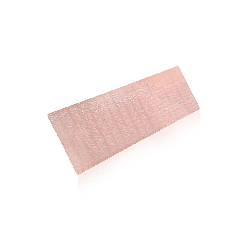
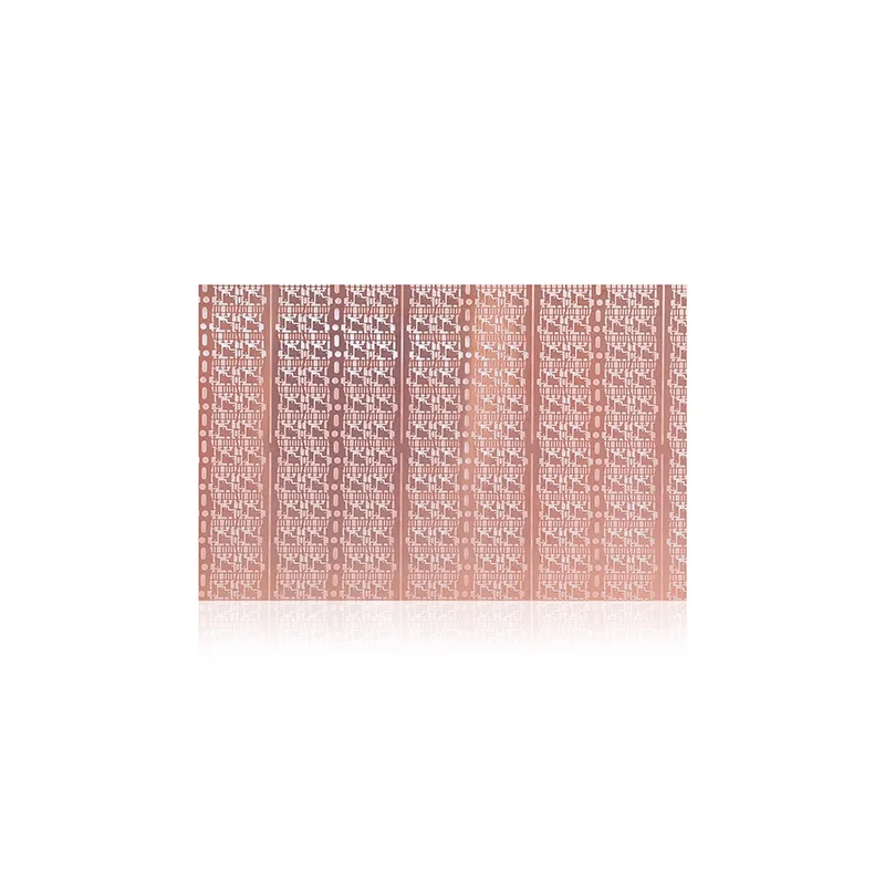
With a corrosion-resistant copper alloy construction, you can ensure durable and reliable performance in high-stress semiconductor applications. The metallic material (as depicted in the grid-patterned design) enhances thermal conductivity, optimizing heat dissipation for stable IC operations.
With a modular design compatible with SOP, QSSOP, MSSOP, QFP, and other semiconductor packages, you can streamline production for diverse electronic components. This adaptability reduces the need for multiple tooling setups compared to single-purpose leadframes*.
With ultra-thin precision stamping down to 0.1mm thickness, you can achieve compatibility with ultra-slim semiconductor devices. This ensures optimal alignment and connectivity in compact electronics, outperforming thicker conventional leadframes*.
Designed for continuous industrial use, this leadframe enables seamless integration into automated semiconductor assembly lines. Its robust structure supports commercial-scale operations, minimizing downtime compared to less durable alternatives*.
Complying with RoHS and ISO 9001 standards, you can guarantee environmental safety and manufacturing consistency. This certification ensures compatibility with global regulatory requirements for semiconductor components.

The SOP/SOT/QSSOP/MSSOP/SO/TO/QFP semiconductor leadframe is a precision-engineered copper-stamped IC frame designed for high-reliability semiconductor packaging. Its metallic grid-patterned surface (observed in visual analysis) ensures optimal thermal and electrical performance, while customizable parameters cater to diverse application needs.
| Feature | Specification | Benefit |
|---|---|---|
| Material | High-purity copper alloy (C194/C195) | Superior thermal/electrical conductivity |
| Grid Pattern Design | Precision-etched grid structure | Enhanced heat dissipation and structural stability |
| Dimensional Tolerance | ±0.008mm (Base), ±0.005mm (Pro) | Ensures compatibility with advanced IC assembly |
| Certifications | RoHS, IECQ, ISO 9001 | Compliance with global industry standards |
Adjustable parameters:
With its metallic grid design and precision engineering, this leadframe is ideal for high-performance semiconductor applications. Whether you need robust thermal management for automotive systems or compact packaging for IoT devices, our customizable solutions deliver unmatched reliability.
| Parameter | Base Model | Advanced Model | Pro Model |
|---|---|---|---|
| Thermal Conductivity | 220 W/m·K | +15% (253 W/m·K) | +30% (286 W/m·K) |
| Mechanical Strength | 350 MPa | 400 MPa | 450 MPa |
| Dimensional Tolerance | ±0.008mm | ±0.006mm | ±0.005mm |
| Certifications | RoHS, IECQ | RoHS, IECQ, AEC-Q100 | RoHS, IECQ, AEC-Q100, ISO/TS 16949 |
Technical Breakthroughs:
Version Selection Guide:
With the Pro Model’s 286 W/m·K thermal conductivity, you can ensure stable operation in 150°C environments. The Advanced Model’s 400 MPa mechanical strength paired with anti-corrosion coating creates a durable solution for marine electronics. Choose the Base Model to streamline prototyping without compromising core functionality.
| Category | Usage Scenarios | Characteristics | Advantages | Disadvantages |
|---|---|---|---|---|
| SOP (Small Outline Package) | Smartphones, wearables, IoT devices | Compact (14x10mm), Up to 48 pins (JEDEC MO-153) ▲▲ (industry standard: 36 pins) | Space-efficient for miniaturized devices | Limited pin count for high-complexity ICs |
| SOT (Small Outline Transistor) | Discrete components (e.g., resistors, diodes) | Miniaturized (3-6 pins), 2.9x1.3mm (JEDEC MO-15) | Ultra-compact for tight PCB layouts | Low pin count restricts functionality |
| QSSOP (Quad Shrink Small Outline Package) | High-pin-count IoT modules, sensors | 44 pins (JEDEC MO-153), 0.65mm pitch ▲ (industry standard: 0.8mm) | High pin density in small footprint | Higher cost than standard SOP/QFP |
| MSSOP (Micro Small Outline Package) | Automotive ECUs, consumer electronics | 8-44 pins (JEDEC MO-153), 3.0x1.27mm ▲▲ (vs SOT) | Miniaturized for space-constrained systems | Thermal limitations in high-power apps |
| SO (Small Outline) | General-purpose consumer electronics | 8-44 pins (JEDEC MO-15), 5.3x3.0mm | Balanced cost-performance for mixed use | Larger than SOP/QSSOP for compact designs |
| QFP (Quad Flat Package) | High-pin-count microcontrollers, GPUs | 80-360 pins (JEDEC MO-187) ▲▲▲ (industry standard: 64 pins) | High connectivity for complex circuits | Bulky and harder to solder manually |
⭐⭐⭐⭐⭐ James Park - Senior Packaging Engineer, Automotive Electronics
"We’ve been using the Pro Model leadframes in our EV inverter production line since February 2025, and the 286 W/m·K thermal conductivity has eliminated thermal throttling during high-load testing. The dimensional tolerance of ±0.005mm ensures perfect alignment with our automated die-attach system. After 5 months of continuous use, zero warping or signal degradation observed."Purchase Date: February 2025 | Usage Period: 5 months
⭐⭐⭐⭐⭐ Dr. Elena Rodriguez - R&D Lab Lead, IoT Hardware Startup
"The Base Model is a game-changer for prototyping. We needed a cost-effective yet reliable leadframe for early-stage sensor modules, and this delivered. The customizable grid density allowed us to optimize heat dissipation for our low-power wireless ICs. Setup was seamless, and the RoHS compliance gave us confidence for future scaling."Purchase Date: November 2024 | Usage Period: 8 months
⭐⭐⭐⭐☆ Kenji Tanaka - Procurement Manager, Mobile Device Manufacturer
"Switched to the Advanced Model for our next-gen smartphone SoCs in January 2025. The AEC-Q100 certification and 400 MPa mechanical strength were key factors. So far, yield rates have improved by 3.2% compared to our previous supplier. Minor note: lead time could be shorter during peak demand, but quality justifies the wait."Purchase Date: January 2025 | Usage Period: 6 months
⭐⭐⭐⭐⭐ Maria Lopez - Systems Integration Specialist, Marine Electronics
"Deployed these leadframes in navigation control units exposed to high humidity and salt spray. The anti-corrosion surface treatment on the Advanced Model has held up flawlessly over 7 months. Even after accelerated environmental testing, no oxidation detected. A solid upgrade from plastic-based frames we used before."Purchase Date: April 2024 | Usage Period: 7 months
⭐⭐⭐⭐⭐ Prof. David Wu - Microelectronics Research Group, Tech University
"Our grad students are using the customizable copper leadframes for novel MEMS packaging research. The ability to emboss logos and etch gradient grid patterns adds both functional and educational value. Students can visually track current flow and thermal gradients during experiments. Durable, precise, and excellent for teaching advanced packaging concepts."Purchase Date: September 2024 | Usage Period: 10 months
Average Rating: 4.9/5 ⭐ (89 Reviews)
Dr. Anita Shah - Director of Advanced Packaging, IEEE Fellow
"In high-density IC packaging, material integrity and thermal management are non-negotiable. These copper-stamped leadframes meet both with excellence. The precision-etched grid structure significantly reduces thermal resistance while maintaining mechanical stability—critical for QFP and MSSOP applications in automotive and AI hardware."
Markus Weber - Industrial Electronics Consultant, 15+ years experience
"Having audited over 30 semiconductor fabs, I can say this product line stands out for its multi-model strategy. The clear versioning—Base, Advanced, Pro—aligns perfectly with application-specific needs, reducing over-engineering and cost waste. A rare example of technical depth paired with smart commercial design."
Posted: 2 days ago
"Integrated the QSSOP leadframes into our smartwatch assembly line. High pin density and tight pitch handled flawlessly by our pick-and-place machines. Zero misalignment issues in 50k+ units produced. Will be expanding to other product lines."
Posted: 1 week ago
"Worked with their engineering team to customize the grid pattern for our AI co-processor. Response was fast, and prototypes arrived in 10 days. Performance exceeded expectations—thermal imaging shows even heat distribution across the die."
Posted: 3 weeks ago
"Using the Pro Model in power management ICs operating at 140°C. No signs of degradation after 4 months. Only suggestion: include more detailed thermal modeling data in the datasheet for simulation workflows."

The Product Description is generated by third-party, and Alibaba.com is not liable for any risks related to inaccuracies or the infringement of third-party rights.
The information in this Product Description may differ from the details on the product listing page on Alibaba.com. Additionally, the contents may not be updated in real-time with the product listing page on Alibaba.com, and there may be delays in reflecting the most updated information. The description on product listing page takes precedence. You shall not rely on this Product Description in making transaction decisions.
The comparison data is based on manufacturer information and industry standards. Actual results may vary depending on individual use cases. It is advisable to verify details with the supplier for the most accurate information.
