All categories
Featured selections
Trade Assurance
Buyer Central
Help Center
Get the app
Become a supplier
3 axis load sensor
(999+ products available)
Alibaba
Electronic Components, Accessories & Telecommunications
Sensors
Force Sensors & Load Cells
Previous slide
Next slide
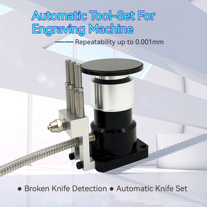
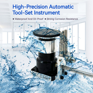
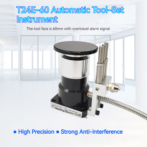
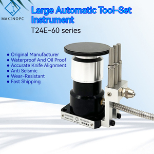
T24E-60 CNC Z
Axis
Zero Tool Setter 60mm Diameter Probe Touch
Sensor
Tool Setting Gauge for CNC Lathe Machining Centers
Ready to Ship
$370-379
Min. order: 1 piece
Previous slide
Next slide
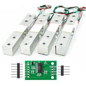
SC902 Small Weight
Sensor
Miniature Flat
3
Wire
Load
Cell
Sensor
50Kg 200Kg For Personal Body Scale
$0.25-0.70
Min. order: 100 pieces
Previous slide
Next slide
GALOCE GSB205 Kit Animal Scale Weighing Scale
Sensor
3
Ton Shear Beam
Load
Cell for Livestock
$79-84
Min. order: 1 set
Previous slide
Next slide
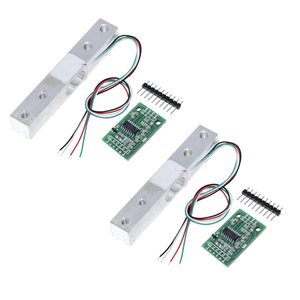
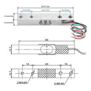
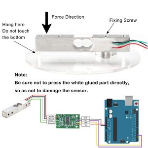
AM31A 12.7mm * 12.7mm * 80mm High Precision Miniature
Load
Cells for Arduino DIY Electronic Portable Kitchen Scale
Sensors
$1.20-3.80
Min. order: 10 pieces
Previous slide
Next slide
6-
Axis
Force
Sensor
3D Triaxial
Load
Cell for Robotics Intelligent Arms Joint Detection & Processing
Ready to Ship
$379.86
Min. order: 1 piece
Previous slide
Next slide
Alloy Steel Stype Beam 1t 3t 5t Loadcell Tension Force
Sensors
Compression Weight
Sensor
s Type
Load
Cell with mV Output
$6-34
Min. order: 1 piece
Previous slide
Next slide
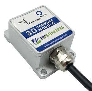
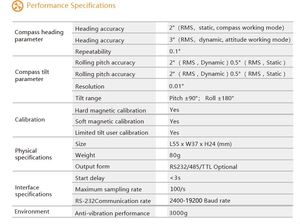
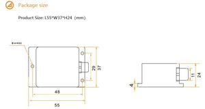
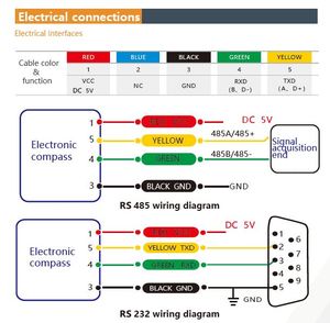
BWSENSING Full Attitude
3
-
Axis
Accelerometer Magnetometer Gyro Electronic Compass
Sensor
SEC295
3
Accuracy All Attitude
Ready to Ship
$70-80
Previous slide
Next slide
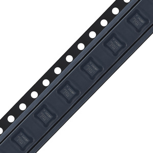
Original ICM-42688-P LGA-14 6-
axis
MEMS Motion
Sensor
,
3
-
axis
Gyroscope +
3
-
axis
Accelerometer
$2.40-2.70
Min. order: 1 piece
1
2
3
4
5
More pages
27
Top categories
Electronic Accessories & Supplies
Audio Components and Products
Power Supplies
Telecommunications
Development Boards, Electronic Modules and Kits
Discrete Semiconductors
Displays, Signage and Optoelectronics
Passive Components
Sensors
Wireless & IoT Module and Products
PCB & PCBA
Circuit Protection
Connectors, Terminals & Accessories
Isolators
RF, Microwave and RFID
Relays
Previous slide
Next slide