
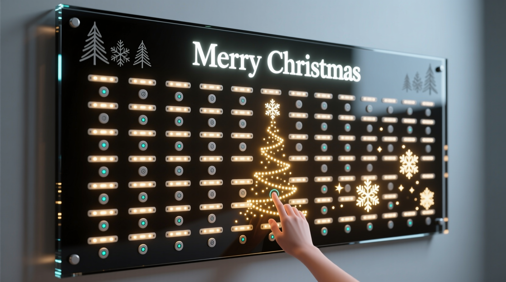
Transform your holiday decor into a dynamic experience by building an interactive Christmas light wall that responds to human touch. Using Arduino and capacitive touch sensors, you can create a festive installation where lights illuminate as fingers approach or touch designated points on the wall. This project blends electronics, creativity, and seasonal charm—perfect for tech-savvy decorators, educators, or makers looking to impress at holiday gatherings.
Unlike traditional static displays, this setup detects proximity or direct contact without physical buttons, offering a seamless and modern aesthetic. Whether mounted in a living room, storefront, or classroom, an interactive light wall invites engagement from guests of all ages. The system is scalable, customizable, and built with affordable, widely available components.
Understanding Capacitive Touch Sensing
Capacitive touch sensing works by detecting changes in electrical capacitance caused by the presence of a conductive object—like a human finger. When a person approaches a sensor pad, their body alters the local electrostatic field, which the sensor registers as a trigger event. This technology powers smartphone screens, touch lamps, and now, your holiday display.
In this project, we use Arduino-compatible capacitive sensors (either via dedicated breakout boards or software libraries) to monitor multiple touch points across a wall surface. Each sensor connects to a metal pad—such as copper tape, foil, or conductive paint—that acts as the user interface. Upon detection, the Arduino activates corresponding LED strands, creating a responsive lighting effect.
“Capacitive sensing turns ordinary surfaces into interactive zones. It’s not just functional—it adds wonder.” — Dr. Lena Torres, Embedded Systems Engineer, MIT Media Lab
The beauty of capacitive sensing lies in its flexibility. You don’t need full contact; even hovering a hand near the sensor can activate lights, enabling gesture-like control. For a Christmas theme, imagine stars that glow when touched, or a snowflake pattern that brightens as children wave nearby.
Components and Setup Overview
Before diving into assembly, gather all necessary hardware and tools. Most items are readily available from electronics retailers or online marketplaces like Adafruit, SparkFun, or Amazon.
Required Components
- Arduino Uno or compatible board (e.g., Nano, Leonardo)
- CapacitiveSensor library (software-based solution) or MPR121 breakout board (dedicated IC)
- Flexible RGB LED strip (WS2812B/Neopixels recommended)
- Jumper wires (male-to-female and male-to-male)
- Resistors (1–10 MΩ for RC circuits if using software method)
- Copper tape, aluminum foil, or conductive paint
- Power supply (5V, sufficient amperage for LEDs)
- Breadboard (optional, for prototyping)
- Wooden frame, foam board, or drywall section (as base structure)
- Hot glue gun, scissors, masking tape
Choosing Between Software and Hardware Sensing
You have two primary options for implementing capacitive sensing:
| Method | Pros | Cons | Best For |
|---|---|---|---|
| Software (CapacitiveSensor Library) | Low cost, uses standard Arduino pins | Limited to ~4–5 reliable sensors; sensitive to noise | Small installations, beginners |
| Hardware (MPR121 IC) | Supports 12 electrodes, stable performance, daisy-chainable | Slightly higher cost, requires I²C knowledge | Large walls, professional builds |
For most DIY users, starting with the CapacitiveSensor library is practical. As your design grows, consider upgrading to the MPR121 for improved reliability and scalability.
Step-by-Step Build Guide
Follow this sequence to assemble and program your interactive light wall.
- Design the Layout: Sketch your wall design—stars, trees, letters, etc. Assign one sensor per element. Space them at least 6 inches apart to avoid crosstalk.
- Prepare the Base: Mount a flat surface (foam board or plywood) on the wall. Outline each decorative shape lightly with pencil.
- Apply Sensor Pads: Cut copper tape or foil into shapes matching your design. Attach securely using adhesive backing or spray mount. Leave a small tab for wire attachment.
- Wire Sensors to Arduino: Connect one end of a wire to each sensor pad (solder or use conductive glue). Route all wires neatly to the Arduino location. If using software sensing, connect through high-value resistors (e.g., 10 MΩ) between send and receive pins.
- Connect LED Strip: Attach the data input of the WS2812B strip to a digital pin (e.g., Pin 6). Link power and ground lines to a common 5V supply. Do not power LEDs directly from Arduino unless minimal length.
- Upload Test Code: Program the Arduino to detect touches and respond with simple light effects. Verify each sensor independently before final integration.
- Mount LEDs Decoratively: Adhere LED strips along the edges of each shape. Conceal wiring behind the board or under trim.
- Finalize Enclosure: Cover exposed electronics in a ventilated box. Label connections for future troubleshooting.
Programming Logic and Custom Effects
The magic happens in code. Below is a simplified example using the CapacitiveSensor library to manage three touch points and control Neopixel LEDs.
#include <CapacitiveSensor.h>
#include <Adafruit_NeoPixel.h>

#define LED_PIN     6
#define NUM_LEDS    30
Adafruit_NeoPixel strip = Adafruit_NeoPixel(NUM_LEDS, LED_PIN, NEO_GRB + NEO_KHZ800);

// Define sensors (send, receive)
CapacitiveSensor  sensor1 = CapacitiveSensor(2, 3);
CapacitiveSensor  sensor2 = CapacitiveSensor(4, 5);
CapacitiveSensor  sensor3 = CapacitiveSensor(7, 8);

void setup() {
  Serial.begin(9600);
  strip.begin();
  strip.show(); // Initialize all pixels to 'off'
}

void loop() {
  long val1 = sensor1.capacitiveSensor(30);
  long val2 = sensor2.capacitiveSensor(30);
  long val3 = sensor3.capacitiveSensor(30);

  if (val1 > 1000) { flashRange(0, 9, strip.Color(255, 0, 0)); } // Red for star
  if (val2 > 1000) { flashRange(10, 19, strip.Color(0, 255, 0)); } // Green for tree
  if (val3 > 1000) { flashRange(20, 29, strip.Color(255, 255, 255)); } // White for snow

  delay(10);
}

void flashRange(int start, int end, uint32_t color) {
  for (int i = start; i <= end; i++) {
    strip.setPixelColor(i, color);
  }
  strip.show();
  delay(200);
  strip.clear();
  strip.show();
}
This sketch reads capacitance values and triggers color-specific animations when thresholds are exceeded. Adjust threshold values (> 1000) based on real-world testing—humidity, material thickness, and wire length affect sensitivity.
To enhance interactivity, expand the code to include fading, chasing patterns, or sound cues via a buzzer. Libraries like FastLED offer advanced animation controls for more dramatic effects.
Real-World Example: A School Holiday Exhibit
A middle school STEM teacher in Portland, Oregon, led students in building a 4' x 6' interactive light wall titled “Touch the Holidays.” Twelve copper-star sensors were placed across a painted backdrop. Each star, when touched, lit up in sequence with accompanying jingle snippets played through a small speaker.
Using an Arduino Mega and MPR121 controller, the team mapped each sensor to a unique LED segment and audio file stored on a microSD card (via VS1053 module). Students decorated the frame with recycled materials, aligning with an eco-theme.
The exhibit debuted at the school’s winter fair and became a hit with younger children, who delighted in \"activating\" the night sky. Teachers noted increased engagement in electronics lessons afterward, proving that hands-on projects deepen learning.
Troubleshooting and Optimization Tips
Even well-designed systems encounter issues. Here are common problems and fixes:
- False Triggers: Caused by electrical noise. Add shielding (grounded foil layer behind sensors), shorten wires, or increase debounce delays.
- No Response: Check continuity of sensor wires. Ensure resistor values are correct and firmware thresholds are properly calibrated.
- LED Flickering: Often due to insufficient power. Use a dedicated 5V supply with adequate current (e.g., 2A for 60 LEDs). Add a 1000µF capacitor across power rails to smooth voltage spikes.
- Limited Range: Increase sensor size or apply conductive paint for larger detection areas. Avoid insulating layers thicker than 3mm over pads.
Checklist: Final Verification Before Launch
- ✅ All sensor pads securely attached and wired
- ✅ No loose connections or exposed solder joints
- ✅ Power supply matches LED strip voltage and current needs
- ✅ Arduino programmed and tested with serial monitor feedback
- ✅ Lights respond accurately to touch or proximity
- ✅ Wall structure safely mounted and stable
- ✅ Emergency power cutoff accessible
Frequently Asked Questions
Can I make the wall respond to gestures, not just touch?
Yes. Capacitive sensors can detect proximity—typically up to 1–3 cm depending on pad size and environment. By tuning sensitivity in code, you can trigger lights when a hand hovers near a symbol, enabling a “touchless” experience ideal for public spaces.
Is it safe to install this around children?
Absolutely. The system operates at 5V DC, which is low-voltage and non-hazardous. Just ensure all high-current power supplies are enclosed and out of reach. Avoid sharp edges on mounting materials.
Can I use washable paint over copper tape?
Only if the paint is non-conductive. Conductive paint will short adjacent traces. If aesthetics demand coverage, seal copper with clear acrylic first, then apply decorative paint on top. Always leave a test point exposed for maintenance.
Conclusion: Bring Magic to Life This Holiday Season
An interactive Christmas light wall powered by Arduino and capacitive sensing bridges art and engineering in a joyful way. It transforms passive decoration into participatory celebration, sparking curiosity and delight. With accessible tools and open-source code, anyone—from hobbyists to educators—can build a stunning centerpiece that stands out in a sea of blinking lights.
Start small, iterate often, and let creativity guide your design. Whether you’re teaching kids about circuits or surprising family with a smart holiday feature, this project proves that technology can be warm, personal, and deeply festive.


 浙公网安备
33010002000092号
浙公网安备
33010002000092号 浙B2-20120091-4
Comments
No comments yet. Why don't you start the discussion?