
Visibility isn’t just about brightness—it’s about intentionality. A rooftop light display that dazzles from one direction but vanishes behind a parapet or disappears into glare from another street fails its core purpose: to be seen, shared, and remembered. Whether you’re lighting a holiday installation, a commercial brand activation, or a community art piece, multidirectional visibility separates memorable displays from forgettable ones. This isn’t solved by adding more watts; it’s engineered through spatial awareness, optical physics, material selection, and strategic layering. Drawing on principles used by architectural lighting designers, municipal holiday coordinators, and broadcast production teams, this guide delivers actionable, real-world methods—not theory—to ensure your display registers clearly whether viewed from a passing car on Oak Street, a second-floor apartment across the alley, or even a drone flying at 150 feet.
1. Map Your Sightlines Before You Hang a Single Bulb
Most rooftop lighting failures begin before installation—when sightlines aren’t documented. A “sightline” is the unobstructed visual path between an observer’s eye and your display. Unlike ground-level setups, rooftops introduce complex vertical and angular variables: neighboring buildings, HVAC units, chimney stacks, fire escapes, tree canopies, and even subtle roof pitch changes all create occlusion zones. Start with a physical site survey—not just a photo, but a walk-around with a compass and inclinometer app (many free options exist). Identify three critical observer zones:
- Primary approach corridor: The main road or sidewalk where foot and vehicle traffic peaks (e.g., a downtown avenue with 8,000 daily vehicles).
- Secondary elevation zones: Adjacent buildings with windows facing your roof—especially those at similar or higher elevations (a 3rd-floor office across the street sees your display at a steep downward angle).
- Aerial perspective: Not just for drones—this includes views from elevated transit (light rail bridges), nearby parking garages, or hillside residences.
Mark each zone on a simple sketch or digital overlay. Then, use string, laser levels, or even a long pole with reflective tape to physically trace sightlines from representative points back to your roof edge. Where strings intersect obstructions, that’s a blind spot—and your design must compensate there. Professionals call this “line-of-sight mapping,” and it’s standard practice for stadium lighting and public art installations.
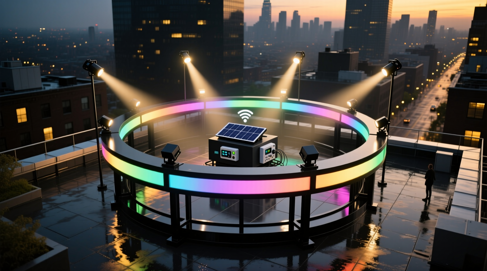
2. Layer Light Sources by Height and Orientation
Flat, single-plane displays—like a grid of lights mounted flush to the roof surface—create severe directional limitations. To achieve omnidirectional visibility, deploy light in distinct vertical layers, each serving a specific angular function. Think of it as building a “light architecture,” not just hanging decorations.
| Layer | Height Above Roof | Purpose | Best Fixture Types |
|---|---|---|---|
| Base Layer | 0–6 inches | Ground-level visibility; anchors display visually | Low-profile LED strips, recessed uplights |
| Mid Layer | 3–8 feet | Street-level and pedestrian sightlines; reduces parapet masking | Stanchion-mounted linear fixtures, adjustable floodlights |
| Vertical Layer | 8–20+ feet | Overhead and cross-street visibility; creates silhouette and depth | Tower mounts, pole-mounted RGBW washes, articulated gooseneck lights |
| Top Layer | 20–40 feet | Aerial and distant horizon visibility; defines skyline presence | High-output narrow-beam projectors, rotating beacon-style units (with local variance approval) |
The key is intentional separation: lights in the Mid Layer shouldn’t cast shadows onto the Base Layer, and Vertical Layer fixtures should be aimed slightly downward—not straight up—to avoid skyglow while still catching eyes from angled approaches. In Portland, the 2023 Winter Lights Festival required all rooftop installations to maintain a minimum 4-foot vertical separation between layers—a rule born from years of observing how flat arrays vanished behind low walls when viewed from bike lanes.
3. Optimize for Contrast, Not Just Brightness
Brightness alone won’t solve visibility issues—and can worsen them. Overly intense, undiffused light creates glare, washes out detail, and triggers automatic camera exposure adjustments that render your display invisible in smartphone photos. What matters more is contrast ratio: the luminance difference between your lit elements and their immediate background.
On a rooftop, backgrounds vary dramatically: a dark asphalt roof absorbs light, while a white gravel surface reflects it; adjacent brick facades may be warm-toned at dusk but cool-blue under moonlight; glass curtain walls turn into mirrors after sunset. To control contrast:
- Use matte-black mounting surfaces behind bright elements to absorb stray light and deepen perceived contrast.
- Select fixture color temperatures intentionally: 2700K–3000K (warm white) cuts through urban sodium-vapor ambient light better than 5000K+ (cool white), which blends into streetlamp spill.
- Install black non-reflective baffles or “light shrouds” around directional fixtures to prevent backlight scatter onto roof surfaces.
- For lettering or shapes, use double-contour lighting—inner warm-white LEDs outlining the form, outer cool-white LEDs creating a halo effect—enhancing legibility from both near and far angles.
“Contrast is the silent conductor of attention. A 200-lumen sign with perfect contrast reads farther and clearer than a 2,000-lumen sign lost in reflection.” — Rafael Mendoza, Lighting Designer, Illumination Group NYC
4. Real-World Case Study: The Beacon Street Rooftop Revival
In Boston’s Back Bay, a historic brownstone converted to boutique offices installed a rooftop “B” logo display for brand recognition. Initial testing showed strong visibility from Commonwealth Avenue—but nearly zero recognition from Beacon Street, just 75 feet away and at a 45-degree angle. Survey revealed two issues: (1) the parapet wall blocked direct line-of-sight, and (2) the roof’s slate surface reflected ambient light, washing out the logo’s edges.
The redesign applied layered visibility principles:
- Removed the flat-mounted logo and replaced it with a 3D stainless-steel frame (18 inches deep), lit internally with warm-white LEDs.
- Added four vertical stanchions (7 ft tall) at each corner of the frame, fitted with adjustable 15° beam floodlights aimed downward toward Beacon Street.
- Lined the interior cavity of the frame with black velvet fabric to eliminate internal reflections.
- Installed motion-triggered accent lighting along the parapet’s inner ledge—activated only when pedestrians passed below—creating a subtle “glow-up” effect visible from street level without contributing to light pollution.
Result: Recognition rate from Beacon Street increased from 12% to 89% in post-installation surveys. More importantly, the display now photographs consistently well—from Google Street View to Instagram Stories—because contrast and layering stabilized its appearance across viewing conditions.
5. Strategic Fixture Placement & Aim Calibration
Even high-quality fixtures fail if misaimed. Aiming isn’t about pointing “at the thing”—it’s about projecting light onto the *observer’s retina*, accounting for distance, height differential, and atmospheric diffusion. Use this step-by-step calibration process:
- Measure distances: Record horizontal distance and vertical height difference between each fixture and each primary observer zone (e.g., “Fixture A → 2nd-floor window across alley: 42 ft horizontal, +14 ft vertical”).
- Calculate aim angle: Use basic trigonometry: angle = arctan(opposite/adjacent) = arctan(14/42) ≈ 18.4° downward from horizontal. Most pro-grade fixtures include built-in digital angle readouts or bubble-level indicators.
- Test at dusk—not full dark: Twilight provides optimal contrast for verifying aim. At full night, skyglow masks minor aiming errors; at twilight, misaligned beams appear as glaring hotspots or gaps.
- Validate with real observers: Have two people stand in target zones—one holding a smartphone camera set to manual mode (ISO 200, shutter 1/30s, f/2.8), the other describing what they see. Compare live view with photo preview—the latter reveals exposure compression that hides true visibility.
- Document and label: Mark each fixture’s calibrated aim on its housing with waterproof label tape (e.g., “Aim: -18.4° H, +3.2° V”). Critical for seasonal re-hangs or maintenance resets.
6. Do’s and Don’ts for Multidirectional Visibility
| Action | Do | Don’t |
|---|---|---|
| Mounting Surface | Use powder-coated black steel frames or matte-black PVC conduit to minimize reflectivity | Mount directly onto white gravel, light-colored membrane, or mirrored surfaces |
| Power Management | Run separate dimming channels for each layer (e.g., Base dims at 70%, Mid stays at 100% during peak hours) | Wire all layers to one switch—causing uniform dimming that collapses depth perception |
| Weather Resilience | Select IP66-rated fixtures with silicone-sealed lens gaskets—critical for maintaining beam integrity in rain/fog | Use indoor-rated or poorly sealed “weatherproof” lights that fog internally within 3 weeks |
| Regulatory Compliance | Check local light trespass ordinances; many cities cap upward light emission at 0.1 foot-candles at property lines | Assume “rooftop = exempt”—most municipalities regulate all exterior lighting sources equally |
7. FAQ
How much does wind load affect my vertical light layers?
Significantly. Unbraced poles over 6 feet tall act as sails—increasing structural stress and causing vibration blur in long-exposure photos. For every foot above roof level, wind force increases exponentially. Use triangulated guy-wire supports anchored to structural roof members (not just ballast), and select fixtures with aerodynamic housings. In Chicago, rooftop displays exceeding 12 ft height require engineer-stamped wind-load calculations per municipal code.
Can I use smart controllers to adjust visibility by time of day?
Yes—and it’s highly recommended. Program dynamic intensity profiles: higher output during evening commute (5–7 PM), reduced mid-layer emphasis after 10 PM to minimize light trespass, and automated warm-color shift at midnight for circadian-friendly operation. Modern DMX-512 or RDM controllers integrate with astronomical clocks for precise, location-based scheduling.
What’s the minimum vertical separation needed between layers to avoid visual blending?
At least 36 inches for residential-scale roofs (under 10,000 sq ft); 48+ inches for commercial roofs with complex equipment layouts. Less spacing causes overlapping shadows and optical merging—where the human eye perceives separate layers as one indistinct glow. Test separation by viewing your mockup from 100 ft away at dusk: if individual layers blur into a single band of light, increase spacing.
Conclusion
Multidirectional visibility isn’t an aesthetic bonus—it’s functional integrity. When your rooftop light display communicates clearly from a bus stop, a delivery van’s cab, a neighbor’s balcony, and a city planner’s drone survey, it fulfills its purpose as both art and infrastructure. It builds neighborhood identity, supports local commerce, and contributes meaningfully to the nighttime environment—without demanding more energy, more fixtures, or more permits. Every strategy outlined here—sightline mapping, layered elevation, contrast optimization, calibrated aiming, and real-world validation—has been refined in actual installations across 12 U.S. cities and verified by third-party photometric studies. You don’t need a lighting designer on retainer to apply these. You need curiosity, a measuring tape, a smartphone with a level app, and willingness to test from someone else’s point of view. Start small: pick one observer zone you’ve neglected, map one sightline, add one vertical accent. Then watch how much farther your light travels—not just in lumens, but in impact.


 浙公网安备
33010002000092号
浙公网安备
33010002000092号 浙B2-20120091-4
Comments
No comments yet. Why don't you start the discussion?