
In mechanical workshops, quality control labs, and manufacturing environments, precision is non-negotiable. One of the most trusted tools for detecting minute variations in surface alignment or dimensional deviation is the dial indicator. While it may appear simple—a circular face with a needle and numbered increments—misreading it can lead to costly errors in production, assembly, or calibration. Learning to interpret a dial indicator correctly isn’t just about understanding numbers; it’s about developing a mindset of accuracy and consistency.
This guide breaks down the process of reading a dial indicator with clarity and confidence, ensuring you can rely on your measurements whether you're aligning shafts, checking runout, or verifying flatness.
Understanding the Components of a Dial Indicator
Before interpreting readings, it's essential to know what each part does. A standard dial indicator consists of:
- Plunger (or spindle): The movable contact point that translates linear displacement into rotational movement of the needle.
- Main dial face: Displays large graduations, typically in 0.001-inch or 0.01-mm increments.
- Inner revolution counter: Tracks full rotations of the main needle, usually counting in 0.100-inch or 1.00-mm steps.
- Needle (pointer): Rotates around the dial to indicate measurement changes.
- Magnetic base or stand: Holds the indicator securely during use.
The plunger moves perpendicularly when pressed against a surface. This motion drives gears inside the mechanism, turning the needle across the dial. Understanding this mechanical linkage helps anticipate response behavior—such as hysteresis or backlash—and avoid false readings.
Step-by-Step Guide to Reading a Dial Indicator
Accurate interpretation follows a methodical approach. Follow these steps carefully:
- Mount the indicator securely. Use a magnetic base or clamp to fix the body firmly. Any movement during measurement invalidates results.
- Pre-load the plunger. Gently press the tip until there’s slight compression (about 10–20% of total range). This ensures consistent contact and avoids slack in the mechanism.
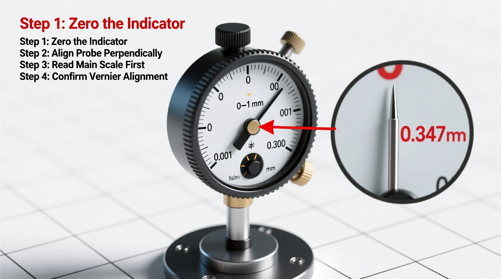
- Set the zero point. Rotate the outer bezel so the needle aligns with “0” on the main dial. Do not adjust the plunger position—only rotate the bezel.
- Take the initial reading. Move the test piece or allow the probe to contact different points. Observe the direction and magnitude of needle movement.
- Track revolutions. If the main needle completes a full circle, note how many times the inner counter advances. Each tick usually represents 0.100 inch or 1 mm.
- Calculate total displacement. Combine the revolution count with the final dial position.
For example, if the inner counter shows +2 and the main needle points to 35 on a 0.001-inch scale, the total reading is:
(2 × 0.100) + (35 × 0.001) = 0.200 + 0.035 = 0.235 inches.
Interpreting Direction: Positive vs. Negative Deflection
A critical aspect often misunderstood is directionality. Most dial indicators register movement relative to the starting (zeroed) position:
- If the plunger retracts (moves out), the needle typically travels clockwise—this is considered a positive reading.
- If the plunger compresses further (moves in), the needle goes counterclockwise—this indicates a negative value.
However, some models reverse this depending on mounting orientation. Always verify direction using a known reference, such as a calibrated shim or gauge block, before relying on readings.
| Needle Movement | Plunger Action | Reading Type |
|---|---|---|
| Clockwise from zero | Retracting (extending) | Positive (+) |
| Counterclockwise from zero | Compressing (pushed in) | Negative (–) |
| No movement | No change | Zero (baseline) |
“Misinterpreting deflection direction is one of the top causes of measurement error in field applications.” — James R. Holloway, Senior Metrology Engineer at Precision Instruments Group
Common Pitfalls and How to Avoid Them
Even experienced technicians occasionally fall into traps that compromise data integrity. Here are frequent mistakes and their solutions:
- Parallax error: Viewing the dial from an angle distorts needle alignment. Always read the dial directly from the front.
- Loose mounting: Vibration or flex in the stand introduces drift. Ensure all clamps are tight and the base is stable.
- Ignoring backlash: Gear-based indicators may have minor play. Always move the probe in one consistent direction when measuring.
- Temperature effects: Thermal expansion affects both the part and instrument. Allow time for acclimatization in controlled environments.
Mini Case Study: Aligning a Lathe Tailstock
A machinist needed to align a tailstock on a manual lathe to prevent tapering during long-turning operations. Using a dial indicator mounted on the carriage, they touched the probe to the tailstock barrel after pre-loading and zeroing.
As the carriage moved along the bed, the needle fluctuated between +0.002\" and –0.001\". The variation indicated misalignment. By adjusting the tailstock set screws incrementally while monitoring real-time feedback, the technician reduced runout to under 0.0005\". The result? Consistent diameter along a 12-inch shaft, eliminating scrap and rework.
This example illustrates how precise dial interpretation directly impacts product quality and efficiency.
Checklist: Best Practices for Accurate Readings
Use this checklist before every measurement session:
- ✅ Securely mount the dial indicator with no wobble
- ✅ Pre-load the plunger slightly (10–20% of travel)
- ✅ Zero the dial using the rotating bezel
- ✅ Confirm needle direction correlates with expected motion
- ✅ Read the dial straight-on to avoid parallax
- ✅ Record both main dial and revolution counter values
- ✅ Clean the probe tip and contact surface before use
- ✅ Calibrate regularly using traceable standards
Frequently Asked Questions
What does one small division represent on a typical dial indicator?
On imperial models, each small graduation commonly represents 0.001 inch. On metric versions, it’s usually 0.01 mm. Always check the scale marked on the dial face.
Can I trust a dial indicator for critical aerospace measurements?
Dial indicators are suitable for comparative measurements and alignment tasks but are generally less precise than digital micrometers or coordinate measuring machines (CMMs). For mission-critical tolerances below ±0.0002\", higher-resolution instruments are recommended.
How often should I calibrate my dial indicator?
For regular industrial use, calibration every 6 to 12 months is advised. In high-precision or regulated environments (e.g., medical or aerospace), quarterly checks may be required.
Conclusion: Precision Begins with Understanding
Reading a dial indicator accurately is more than a technical skill—it’s a discipline. When you understand the mechanics behind the needle’s movement, respect the nuances of direction and preload, and apply consistent methodology, you transform a simple tool into a powerful asset for quality assurance.
Whether you're maintaining machinery, inspecting components, or teaching others, mastering this fundamental instrument elevates your workmanship. Don’t assume the reading is correct because the needle moved—verify setup, confirm direction, and double-check calculations. That extra attention is what separates adequate results from excellence.


 浙公网安备
33010002000092号
浙公网安备
33010002000092号 浙B2-20120091-4
Comments
No comments yet. Why don't you start the discussion?