
Every holiday season, millions of homeowners reach for that familiar box of mini LED lights—only to discover a small, often overlooked warning printed on the packaging: “Do not connect more than 3 sets end-to-end.” Or perhaps it’s 5, 10, or even 21, depending on the brand and bulb type. Few stop to ask why. It’s not marketing caution or legal CYA language. It’s physics—specifically, the interplay of electrical resistance, voltage drop, thermal limits, and safety standards. When you daisy-chain too many strands, you’re not just risking dimmer lights—you’re inviting overheating, premature failure, and in rare but real cases, fire. Understanding the underlying science transforms a simple instruction into an essential safety principle.
The Core Physics: Resistance, Voltage Drop, and Power Distribution
Christmas light strands are low-voltage, series-parallel hybrid circuits—not pure series like old incandescent strings, nor fully parallel like household wiring. Modern LED strands typically group 3–5 LEDs in series (to match forward voltage requirements), then replicate that group dozens of times across the strand in parallel branches. This architecture balances efficiency, brightness, and fault tolerance. But each segment adds resistance—and resistance has consequences.
Copper wire, though highly conductive, is not lossless. Its resistance (R) follows R = ρL/A, where ρ is resistivity, L is length, and A is cross-sectional area. Standard 22–24 AWG stranded copper wire used in light cords has measurable resistance per foot—roughly 0.016 Ω/ft for 22 AWG. A 35-foot strand contains ~70 feet of total conductor path (hot + neutral). That yields ~1.1 Ω of inherent wire resistance *before* any LEDs are considered.
When current flows through that resistance, energy converts to heat via Joule heating (P = I²R). More critically, voltage drops along the length of the cord. If the first socket receives 120 V, the last may see only 108 V—or less—after several connected strands. LEDs require stable forward voltage (typically 2.8–3.4 V per diode). Under-voltage causes flickering, color shift, or complete dropout. Overvoltage—caused by poor regulation or mismatched drivers—can overstress internal current-limiting resistors or ICs.
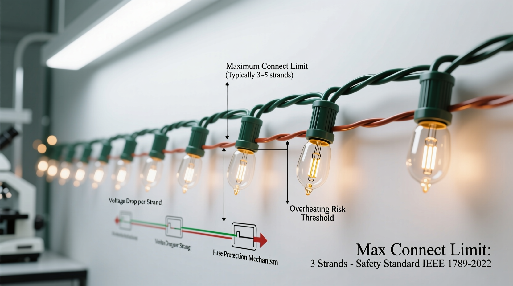
Why LED Strands Still Have Limits (Despite Lower Wattage)
It’s common to assume LED lights eliminate connection limits because they draw far less power: a typical 100-light LED strand uses 4–7 watts, versus 200–400 W for comparable incandescent strings. Yet LED strands still enforce strict daisy-chaining caps—often 40–50 sets for premium commercial-grade lines, but as few as 3–5 for budget retail versions. Why?
The answer lies in two often-overlooked factors: driver design and thermal management. Most plug-in LED strands contain an AC-to-DC converter (a “driver”) housed in the male plug or first bulb housing. This driver must regulate output voltage and current for the entire chain. Cheap drivers use linear regulation or basic capacitor-input rectifiers with minimal filtering. As load increases, ripple voltage rises, regulation degrades, and internal components heat up. Sustained operation above rated load accelerates electrolytic capacitor aging—a leading cause of early strand failure.
Additionally, while individual LEDs run cool, the driver ICs, bridge rectifiers, and current-limiting resistors generate concentrated heat in a tiny enclosure. UL 588 (the U.S. standard for seasonal lighting) mandates surface temperature limits: ≤90°C for accessible parts, ≤120°C for internal components under worst-case conditions. Exceeding the manufacturer’s specified connection count can push these temperatures beyond safe thresholds—even if the strand remains lit.
Real-World Failure: A Mini Case Study from a 2022 Holiday Season
In December 2022, a homeowner in Portland, Oregon, connected 12 identical 35-foot, 200-light LED strands to outline his roofline and garage. The packaging stated “Max 5 sets,” but he reasoned that since each used only 5.2 W, the total load (62.4 W) was trivial compared to a standard 15-amp circuit’s 1,800-watt capacity. He powered the chain from a single outdoor GFCI outlet using a heavy-duty 12-gauge extension cord.
After four hours of operation, the third strand from the plug began emitting a faint acrid odor. Within 20 minutes, its plug housing discolored brown, and the strand went dark. Inspection revealed melted insulation on the neutral wire near the input connector and carbon tracking inside the driver housing. An electrician confirmed the driver had thermally failed due to cumulative voltage ripple and inadequate heat dissipation—exacerbated by cold ambient air limiting natural convection cooling. Crucially, the failure occurred *well below* circuit breaker trip thresholds: total current draw remained under 0.6 amps. The issue wasn’t overload in the ampacity sense—it was localized thermal runaway within a component never designed for that electrical stress profile.
Safety Standards & Engineering Trade-Offs: What UL 588 Requires
The maximum connect limit isn’t self-declared. It’s validated during UL 588 certification testing. To earn the UL mark, manufacturers must submit strands for rigorous evaluation—including continuous operation at 110% of rated load for 168 hours (one week), with temperature probes placed on critical components. The test simulates worst-case ambient conditions: 40°C (104°F) for outdoor-rated lights, 25°C for indoor. Any component exceeding temperature limits—or showing insulation degradation, arcing, or flame propagation—fails.
Manufacturers don’t arbitrarily choose lower limits to reduce liability. They balance three competing priorities:
- Cost: Higher-rated drivers with robust thermal design and oversized capacitors increase BOM cost by 20–40%.
- Size: Effective heat sinking requires larger plug housings—unacceptable for mass-market aesthetics.
- Reliability: Over-engineering for extreme daisy-chaining reduces field failure rates but makes products less price-competitive.
This explains why professional-grade commercial lights (e.g., those used on municipal trees) often permit 40+ connections: they use industrial drivers with aluminum heat sinks, conformal-coated PCBs, and active thermal monitoring. Consumer-grade lights optimize for shelf appeal and $19.99 pricing—not infinite scalability.
“The ‘max connect’ number isn’t about how much power your breaker can handle—it’s about how much heat a $1.27 driver IC can safely shed in a plastic shell while maintaining ±5% voltage regulation across 200 LEDs. Physics doesn’t care about your holiday vision.” — Dr. Lena Torres, Electrical Safety Engineer, Underwriters Laboratories (retired)
Connection Limits by Type: A Practical Comparison Table
| Light Type | Typical Max Connect (Indoor) | Typical Max Connect (Outdoor) | Key Limiting Factors |
|---|---|---|---|
| Incandescent Mini (20–100 lights) | 3–5 strands | 2–3 strands | High wattage (20–40 W/strand); wire gauge limits; thermal buildup in sockets |
| Standard LED Mini (100–200 lights) | 4–10 strands | 3–5 strands | Driver thermal limits; voltage regulation drift; capacitor ripple stress |
| Commercial LED (UL Listed Class 2) | 25–40 strands | 20–35 strands | Aluminum heat sinking; regulated constant-current drivers; wider voltage tolerance |
| Smart LED (Wi-Fi/Zigbee) | 1–3 strands | 1–2 strands | Additional RF circuitry heat; tighter voltage windows for microcontroller stability; signal attenuation over long chains |
| Fairy Lights (battery or USB-powered) | Not applicable (no daisy-chain design) | N/A | Current-limited sources; no AC driver; voltage sag triggers automatic shutdown |
A Step-by-Step Guide to Safe, Scalable Lighting Setup
Want brilliant, reliable light displays without violating physics? Follow this verified sequence:
- Calculate total load: Multiply strand wattage (found on label or UL listing) by number of strands. Confirm it’s ≤80% of circuit capacity (e.g., ≤1,440 W on a 15-A circuit).
- Respect the printed limit: Never exceed the “Maximum Number of Sets” on the UL label—even if math suggests headroom. That number reflects thermal and regulation testing, not just amperage.
- Distribute power: Use multiple outlets or a multi-outlet power strip rated for outdoor use (if applicable) instead of chaining beyond limits. Space outlets at least 25 feet apart along your display path.
- Verify wire gauge: For extension cords powering multiple strands, use 12-gauge for runs >50 ft or >10 strands; 14-gauge only for short, light loads. Never use 16-gauge “lamp cord” for permanent outdoor setups.
- Test incrementally: Power up 1–2 strands first. Wait 15 minutes. Check plug housings for warmth. If warm to the touch (>40°C / 104°F), reduce the chain length or add a second circuit point.
- Inspect annually: Before storage, examine plugs for discoloration, brittleness, or bent prongs. Discard any strand showing signs of thermal stress—even if it still lights.
FAQ: Physics-Based Questions Answered
Why don’t manufacturers just use thicker wire to eliminate voltage drop?
They could—but thicker wire increases cost, weight, and stiffness, making strands harder to drape and store. More critically, voltage drop is only one factor. Driver thermal limits dominate modern LED strand ratings. Thicker wire wouldn’t solve capacitor aging or regulator instability under ripple stress.
If I’m using a 12V DC system with a separate power supply, do connection limits still apply?
Yes—but the limits change. Low-voltage systems are far more sensitive to voltage drop: a 0.5 V drop on 12 V represents 4% loss, enough to dim LEDs noticeably. Manufacturer-specified max lengths (e.g., “do not exceed 16 ft per run”) reflect wire gauge and acceptable voltage sag—not just heat. Always use the power supply recommended for your specific strand model.
Can I bypass the limit by splicing wires directly instead of using the built-in connectors?
No. Splicing voids UL certification, creates untested junction points prone to corrosion and arcing, and eliminates the strain relief and polarization safeguards built into molded connectors. It also violates NEC Article 400.7 (uses permitted for flexible cords) and most residential insurance policies.
Conclusion: Respect the Equations, Not Just the Instructions
The maximum connect limit on your Christmas lights isn’t a suggestion. It’s a hard boundary drawn by Ohm’s Law, Joule’s First Law, and decades of empirical failure analysis. Every time you ignore it, you’re asking physics to compromise—on your behalf, your home, and your family’s safety. But understanding the “why” transforms compliance from chore to conscious craftsmanship. You gain the confidence to design smarter displays: using distributed power, selecting grade-appropriate strands, and recognizing when “more lights” means “better engineering”—not just longer chains. This holiday season, let your lights shine brightly—not because you pushed the limits, but because you honored the science that keeps them safe, stable, and spectacular.


 浙公网安备
33010002000092号
浙公网安备
33010002000092号 浙B2-20120091-4
Comments
No comments yet. Why don't you start the discussion?