All categories
Featured selections
Trade Assurance
Buyer Central
Help Center
Get the app
Become a supplier
(3307 products available)

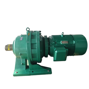
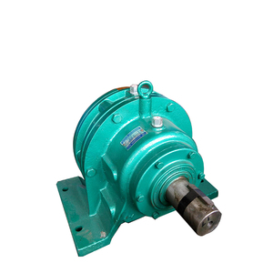


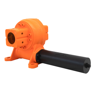
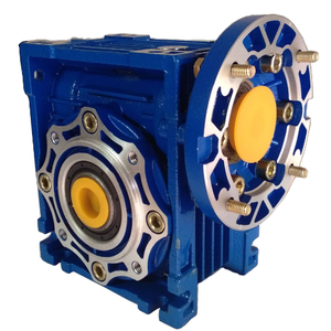
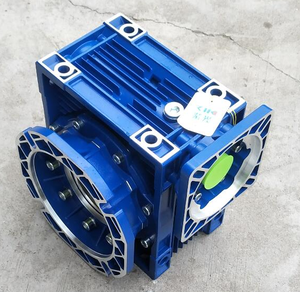


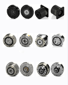
Vertical cycloidal speed reducers are key components in many industries. They give strong power while making the process run smoother, efficiently, and quietly. Here are the common types of vertical cycloidal speed reducers.
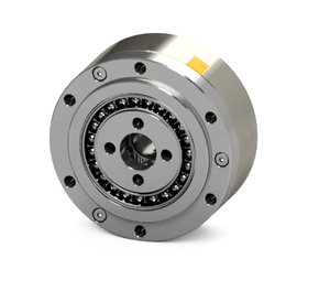
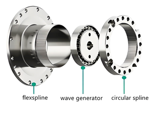
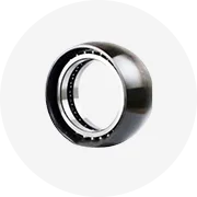
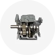
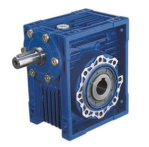
A cycloidal gear speed reducer is a high-efficiency device. It uses an eccentric cam to drive cycloidal pins for power transmission. Unlike regular gears, which may slip or wear out fast, these reduce speeds with less heat and more torque. Less moving parts mean it lasts longer. That's why artisans in robotics, automation, and aerospace all pick it for their projects. The lighter and smaller design also saves space in machinery systems, especially where every inch counts.
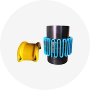
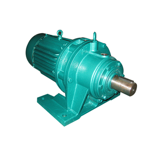
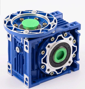
It is a special multipliers used for cycloidal drives. It steps up the input speed by spreading the power among more output pins. This even speed distribution lowers the chances of one pin wearing out too soon like traditional multiplers. They are great for light power tools. It helps make the tools work faster without overloading one pin. Its efficient design uses less energy to complete tasks faster. Repair and maintenance become easier as well.
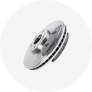
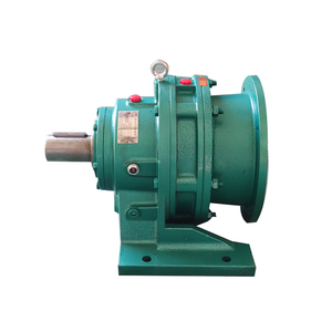
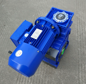
The cycloidal gearbox with brakes also features an inbuilt braking system. The brake helps hold or control the machine load when pause or slow movement is needed. The gearbox and brake work together smoothly, still transmitting power. It's used in lifts and cranes where safety is vital. It secures the load even if power cuts out. This improvement makes it a popular choice for safety in heavy industries.
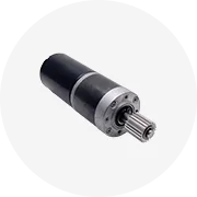
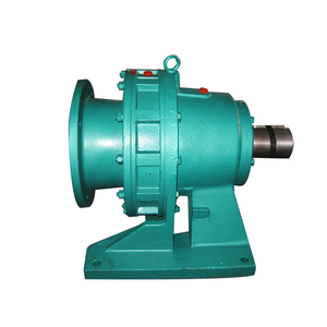
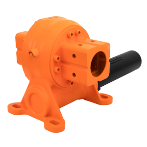
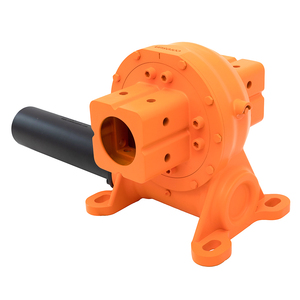
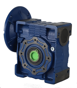
The double output shaft cycloidal gearbox has two output shafts. They both share the load equally. This design improves stability and makes heavy loads easier to turn. It can also power two different tools or parts from one source. Large manufacturing machines and construction gear that needs more power use this gearbox. It makes the system more reliable and less likely to break when under heavy use.
Vcycloidal speed reducer verticals are widely used in countless industries. They give precision control while carrying hefty loads. Following are the common applications of cycloidal speed reducer vertical.
They are used to give robots and automated machines the power to move. They allow the machine arms and tools to turn with great accuracy and strength. This makes assembling cars, electronics, and delicate equipment faster and better. Their compact size helps them fit into the small spaces of modern machines. This helps factories maximize production with fewer workers and machines.
The vertical speed reducers help the cutting tools in CNC machines move precisely. By slowing down the motor speed and magnifying the power, the reducers enable smooth, exact cuts in metal and other materials. This achieves clean edges, detailed work, and consistent results in product making. Consistency and precision help reduce the need for manual work and material wastage. They make mass production in factories efficient.
When conveyors run, the cycloidal speed reducer moves the load-carrying belts. All the boxes and products are transported using these systems. These reducers keep the motors from overload as mulitple items are transported. They ensure steady movement and limit wear and tear on the parts. They are used in warehouses, factories, and shipping centers to improve efficiency and reliability.
Gear Ratio
The gear ratio determines how much the input speed will be reduced. It can range from 11:1 to 90:1 depending on the model. The higher the ratio, the greater the speed reduction.
Output Torque
Output torque is the twisting force provided at the output shaft. This is expressed in Newton meters (Nm). Multiplying the input torque by the gear ratio gives the output torque.
Efficiency
Efficiency indicates how well the reducer converts input power to output power. A high efficiency, such as 94% or more, means less energy is wasted as heat.
Maximum Input Speed
This is the highest allowable speed at the input shaft. Common values are 1000 to 3000 RPM. The speed must not exceed this limit to prevent damage.
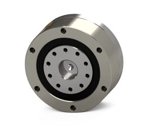
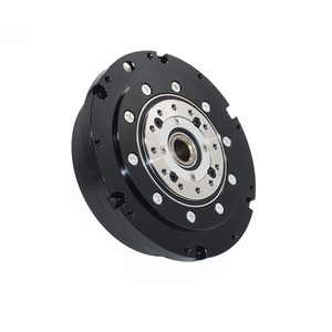
Output Flange
This mounting feature allows direct attachment of loads, such as motors or tools, to the output shaft.
Preparation
The area where the reducer is to be mounted should be clean, free from debris and have no moisture build up. The mounting surfaces should be checked to ensure they are level and flat.
Mounting
The reducer should be attached to the machine base or a bracket using bolts. The bolts should be tightened evenly to ensure the reducer is secured without wobbling.
Input Connection
The input shaft of the reducer should be connected to the motor. To secure this connection a coupling or directly mounting the motor's shaft can be done. The motor should be mounted per the manufacturer's guidelines.
Output Connection
The output shaft should be attached to the load, such as a rotating element. Care should be taken so not to misalign or over tighten the connection.
Alignment Check
The alignment of the input and output shafts with respect to each other should be checked. Any misalignment can cause premature wear and vibration.
Lubrication
The lubricant used by the speed reducer should be verified. The oil level should also be inspected to ascertain that it is at the recommended level.
Safety Cover
Any covers or guards that came with the reducer should be installed back. This will protect the internal components from external elements.
Power Connection
The motor should be connected to the power source. The reducer should then be run at low speed to check for any unusual noises or vibrations.
Maintenance
The following care tips can be used to increase the lifespan of cycloidal speed reducer vertical.
Lubrication: Lubricant helps reduce friction. The type and level should matched for proper functioning. The lubricant should be checked at intervals and replaced based on manufacturer's advice. The presence of dirt should be looked for as it can cause parts to wear out.
Inspection: It is important to visually check the reducer for signs of damage. No parts should be leaking nor should there be any build up of foam. Noise and vibration level should also be noted as any significant changes may indicate problems. Caught soon enough these can prevent total breakdowns.
Temperature Monitoring: The operating temperature should be kept in check. Excess heat can lead to part failure and reduce efficiency. If the reducer feels hotter than normal it should be investigated. Heat dissipation may be required.
Seals and Gaskets: The seals and gaskets hold lubricants inside where they belong. Any cracks, wear or looseness means they should be replaced as soon as possible so the lubricant does not leak out.
Repair
Some repair tips to consider include maintaining the following.
Component Replacement: Internal components like gears or bearings wear out over time. Repair means replacing these worn out parts before total failure happens. Official replacement components must be used according to the company to avoid issues.
Housing Repair: Any visible damage to the housing, such as cracks, must be fixed. Small cracks can grow into big problems. Patching or welding may be possible for minor damage. Bust major cracks need a full housing replacement to prevent internal part migrations or exposure.
DIY Fixes
Cycloidal speed reducer verticals that are damaged beyond repair usually require professional help. However, there are a few DIY hacks that can also come handy. For instance, gaskets and seals can be replaced at home. One just needs to ensure they are purchased from trusted sources and fitted properly.
When selecting the vertical cycloidal speed reducers, several factors should be considered. These help buyers make an informed decision that aligns with the needs of their unique applications.
The specific application of the reducer should be considered. The weight of the load, required speed, and torque of the application should be analyzed. This gives a clear picture of the expectations from the reducer. Knowing the environment the reducer will be operating in goes a long way too. Factors like moisture, dust, and heat can adversely affect its performance and durability. Hence, applicable enemd protection ratings should be noted.
The gear ratio is a key factor as it determines the magnitude of the speed reduction. The ratio should be compatible with the speed range of the motor being used. A higher ratio will provide greater torque and slower speed. In contrast, a lower ratio will result in increased speed with less torque. One must consider the motor's input speed. It must not exceed the maximum input speed of the reducer.
The maximum output torque is another important consideration. It needs to be compared with the application's torque requirements. Selecting a reducer that can provide greater output torque than is needed narrows down the choices. However, going for one that provides less output torque than is needed can bring catastrophic results. Using a motor with too much torque for the reducer can cause damage due to excess force. On the other hand, using a motor that is unable to meet the required torque can result in overloading and ultimately killing the reducer.
The materials used to make the reducer have a huge impact on its longevity. Buyers should go for options that come with higher-quality materials. For example, stainless steel and aluminum have great tensile strength and can easily bear mechanical loads. So, they will not get deformed nor will they corrode over time. In case the reducer operates in a harsh environment, those with hermetically sealed gear cases are an ideal choice. They prevent the infiltration of contaminants like dust and moisture.
Slight variations in the design can have a huge impact on the performance of the reducer. Therefore, a vertical positioning at the right angle index are crucial. While going for one, buyers should make sure the cycloidal discs are of equal length. This ensures the load is evenly distributed. In case the discs have one longer than the other, they must be positioned shafts horizontally to offset the load. The input and outputshafts must also be parallel to each other to avoid stressing the bearings.
Yes, speed reducers can work as speed amplifiers by lowering the input speed while increasing the output torque. A typical example is robotic applications. Here the input speed from the motor is reduced while maximizing the output torque thereby smoothly moving loads with high torque requirements at relatively low speeds. Just ensure it is correctly matched with a high-speed motor to effectively amplify the torque without surpassing the maximum input speed limit.
Braking options for speed reducers that have been integrated into braking systems include mechanical brakes and non-conventional electromagnetic and eddy current brakes. Mechanical brakes include drum brakes and disc brakes. They clamp the output shaft and completely lock its movement. This method is considered very basic. One of the most utilized braking systems is the electromagnetic brake. It operates by generating a magnetic field that pulls a brake pad against the output shaft. Eddy current brakes utilize fast rotating conductors to create internal currents. These currents then generate opposing magnetic fields to smoothly absorb energy. The choice of braking system depends on the specific application requirements including space constraints, load characteristics, and precisely how much controllable motion is needed.
Efficiency mainly depends on the construction quality and materials used rather than orientation. Vertically mounted speed reducers can have the same efficiency as horizontally mounted ones. Ultimately, whether one design is more efficient than the other depends on the application requirements and constraints, such as space availability, orientation, and positioning rather than just efficiency alone.
The braking capacity of speed reducers can be boosted by making several modifications. The first option is increasing the force or torque the braking system can handle. This can be done by employing a brake with a wider friction surface or using more sophisticated braking material with higher friction coefficients. Another option is to integrate a braking mechanism directly onto the output shaft. This minimizes energy loss while boosting braking power. Lastly, adding a brake booster that utilizes fluid, electric, or pneumatic power to amplify the force exerted on the brake is also a great option. All these modifications should only be adopted after careful consideration of the application requirements and environmental factors. They are likely to undergo frequent maintenance if they are not designed for low brake wear cycle.
To increase the lifespan of speed reducers, the first things users should strive to do is keep them free from contaminants like dust or moisture. This can be achieved by regularly inspecting seals and gaskets and replacing damaged ones immediately. Worn out internal components are one of the major predisposes of speed reducer failures. To prevent this from happening, users should use only high-quality components when making any repairs. Using poor-quality materials tends to attract speed reducer failure sooner rather than later. Furthermore, opting for lubricants with low-quality viscosity can increase components wear due to metal-to-metal contact as they will not be able to properly lubricate the internal components. The type of lubricant used should be checked at intervals to ensure it is within manufacturer recommendations. Regularly monitoring for unusual heat generation should also be considered. Excess heat can lead to internal component wear. If the reducer is excessively hot, the root of the problem should be identified and corrected immediately. Last but not least, overloading the speed reducer incapacitates it to perform its core function. The recommended load capacity should never be exceeded.