All categories
Featured selections
Trade Assurance
Buyer Central
Help Center
Get the app
Become a supplier
(936 products available)


 Ready to Ship


 Ready to Ship


 Ready to Ship


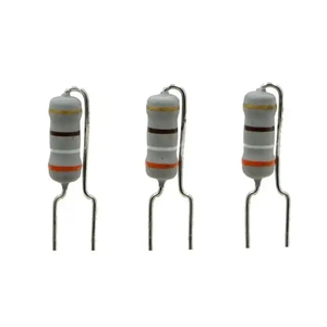
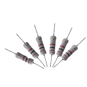
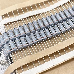
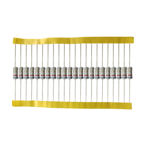
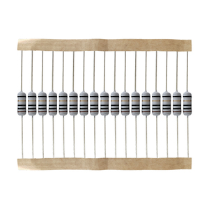
Fuse resistor color code is a method that uses different colored bands wrapped around a resistor to identify its resistance value and other important features. The color bands on a resistor are like a secret code that tells you how much it resists the flow of electricity and how much power it can safely handle. By knowing the colors and what they mean, one can quickly figure out the resistor's value and make sure it's right for the electrical circuit they are working on.
The design of a fuse resistor color code system typically includes several key components and features that enable users to quickly and accurately determine the specifications and ratings of a resistor. Here are some essential aspects of its design:
Color Bands
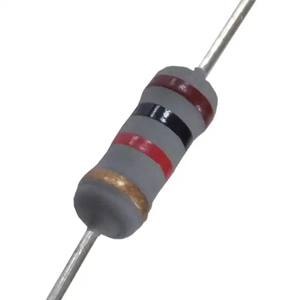
These are the primary means of conveying information in a fuse resistor color code. Typically, resistors use a system of four, five, or six color bands printed on their cylindrical bodies. Each color corresponds to a specific digit or multiplier. For example, in the standard four-band code, the first two bands represent significant digits, the third band indicates the multiplier, and the fourth band denotes tolerance. The colors are universally standardized, with each color representing a specific value. For instance, red might represent the digit 2, while green represents 5.
Orientation and Reading Direction
The design also considers the orientation of the resistor when reading the color codes. Typically, the resistor should be positioned with the leads facing downward. The reading direction starts from the end closest to the band with a specified function (usually the tolerance band) and proceeds towards the other end. This ensures that users consistently interpret the codes in the same way, minimizing errors caused by improper viewing angles.
Code Documentation and Standards
Color coding systems are often accompanied by documentation and standardized tables that specify the meaning of each color and its corresponding value. These tables are widely available and serve as references for technicians and engineers working with resistors. Additionally, industry standards (like EIA-568 for telecommunications) dictate specific coding schemes to maintain consistency across different applications and products.
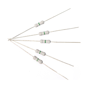
Visual Contrast and Durability
The design prioritizes visual contrast between colors to ensure easy identification by users. The color bands are typically printed using durable inks or coatings to withstand environmental factors like moisture, heat, and mechanical wear. This ensures that the color code remains legible throughout the resistor's lifespan, reducing the likelihood of misinterpretation due to fading or damage.
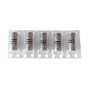
Size and Scale
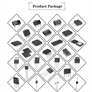
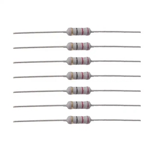
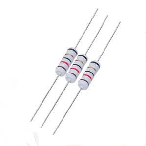
Fuse resistor color codes are designed to accommodate various resistor sizes and power ratings. The scale of the color bands and their spacing are optimized to fit different resistor packages, from small surface mount resistors to larger through-hole types. This scalability ensures that the color coding remains practical and recognizable across a wide range of resistor types and applications.
Accessibility and Training
The design also considers the accessibility of training resources for users unfamiliar with the color coding system. Educational materials, training programs, and online tools are often available to help individuals learn how to interpret the color codes correctly. This promotes a better understanding of the system and reduces the likelihood of errors caused by a lack of knowledge.
Color coding of fuse resistors is vital for interpreting and utilizing them correctly. Here are some suggestions for wearing and matching these elements based on their color codes:
Wearing Suggestions
When wearing a resistor, one must know its color code to select a component with the correct resistance value. Wearers should match the resistor with the right circuit component. For instance, a five-band resistor with a blue, red, and orange band signifies a 247-ohm value. Therefore, users should match the resistor with an LED that requires 240 ohms. Also, users should wear gloves when handling surface mount fuse resistor color codes to avoid damage. Further, they should use a magnifying glass to read the small print clearly. More importantly, they should store spare resistors in an organized manner to prevent confusion. This makes it easy to find and use them when needed. Additionally, users should refer to color code charts regularly to refresh their memory. This ensures they decode the resistor values accurately every time they use them.
Matching Suggestions
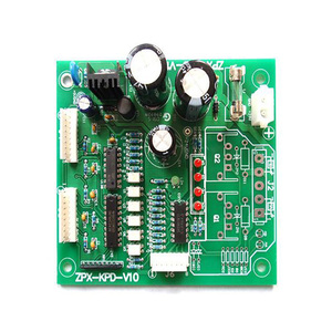
Matching a fuse to its resistor color code requires careful consideration. For example, a fuse with a white and red band usually indicates a low-rating value. So, the user should match it with a resistor that has a high wattage rating. Additionally, the resistor should have a tolerance of 5% or better. More importantly, users should consider the voltage rating of both components. Also, they should ensure the voltage rating of the resistor exceeds the circuit voltage. This prevents damage to the resistor and circuit components. In high-frequency circuits, users should select a low-inductance fuse. This helps to minimize signal distortion. Additionally, they should choose a fuse with a fast blow characteristic. This protects the circuit from short-term overcurrent effects. Similarly, in power applications, they should select a fuse with a slow blow characteristic. This allows for brief inrush currents without blowing. Therefore, protecting the circuit components. Lastly, they should consider the physical size and mounting type of the components. This ensures they fit in the designated space on the PCB.
Q1: How does one identify the value of a fuse resistor using the color code?
A1: To determine the value of a fuse resistor, one must read the color bands. The first two bands indicate significant figures, the third band is a multiplier, and the fourth band shows tolerance. For example, if the first band is red (2), the second is yellow (4), the third is the blue multiplier (10^1), the resistor value is 24 multiplied by 10, which equals 240 ohms with a certain tolerance as indicated by the fourth band.
Q2: What are the typical color codes for high wattage fuse resistors?
A2: High wattage fuse resistors often use the same color coding system as lower wattage ones, but with different standards. Some might follow the EIA-96 standard, which uses a different coding method. Always refer to the manufacturer's specifications to ensure accurate identification.
Q3: Can one use a multimeter to check the value of a fuse resistor?
A3: Yes, a multimeter can be used to measure the resistance value of a fuse resistor. However, the resistor must be removed from the circuit or the power must be turned off to avoid false readings and potential damage to the multimeter.
Q4: What are the implications of a faulty fuse resistor?
A4: A faulty fuse resistor can lead to circuit failure, as it won't protect against overcurrent or maintain the required resistance. This can result in damaged components or complete circuit malfunction.