


Types of Motor Control Units
A motor control unit (MCU) is a crucial component in electric motor systems that manages the operation of motors by regulating speed, direction, torque, and other performance parameters. These units are widely used across various industries such as manufacturing, HVAC systems, material handling, and automation equipment. Choosing the right type of motor control unit significantly impacts system efficiency, reliability, and maintenance requirements.
Key Functions of Motor Control Units:
- Start/stop motor operations
- Regulate speed and torque
- Provide overload and fault protection
- Enable remote or automated control
- Improve energy efficiency and reduce mechanical stress
Manual Motor Control Unit
The simplest form of motor control, typically operated via physical switches, buttons, or rotary controls directly accessible to the operator.
Advantages
- Low cost and simple design
- Easy to operate and maintain
- Minimal setup required
Limitations
- Limited automation capabilities
- No built-in protection features
- Inefficient for frequent or complex operations
Best for: Simple applications like small machinery, manual pumps, or basic workshop tools where precise control isn't critical.
Magnetic Motor Control Unit
Combines an electromagnetic contactor with overload protection relays and control circuitry to enable remote operation and motor safeguarding.
Advantages
- Remote control capability
- Built-in overload and short-circuit protection
- Scalable for high-power industrial applications
Limitations
- More complex wiring and installation
- Higher initial cost than manual units
- Larger footprint compared to compact designs
Best for: Industrial applications requiring reliable motor protection and remote control, such as conveyor belts, compressors, and large HVAC systems.
Soft Starter Motor Control Unit
Designed to gradually increase voltage during startup to reduce inrush current and mechanical stress on the motor and connected equipment.
Advantages
- Reduces electrical and mechanical shocks
- Extends motor lifespan
- Smooth acceleration and deceleration
Limitations
- Does not provide variable speed control
- Less efficient for constant-speed applications
- Higher cost than basic magnetic starters
Best for: Applications involving heavy loads like pumps, fans, and conveyors where smooth starts and stops are essential.
Variable Frequency Drive (VFD)
Advanced electronic devices that control motor speed and torque by varying the frequency and voltage supplied to the motor.
Advantages
- Precise speed and torque control
- Significant energy savings
- Reduced wear on mechanical components
- Programmable settings for optimization
Limitations
- High initial investment
- Requires proper installation and configuration
- Potential for harmonic distortion in power systems
Best for: Energy-intensive systems like HVAC chillers, water pumps, and process control systems where variable speed is needed for efficiency.
Integrated Motor Control Unit
Modern all-in-one solutions combining control, protection, communication, and diagnostics in a single compact device designed for smart automation environments.
Advantages
- Compact and modular design
- Supports digital communication protocols (e.g., Modbus, Profibus)
- Advanced diagnostics and monitoring
- Improved system integration and scalability
Limitations
- Higher complexity requires skilled setup
- Premium pricing compared to traditional units
- May require software support and updates
Best for: Automation systems, smart factories, and advanced process industries where connectivity, precision, and diagnostics are key requirements.
| Type | Control Type | Protection Features | Speed Regulation | Best Application |
|---|---|---|---|---|
| Manual MCU | Direct Operator Input | Limited or None | No Speed Control | Simple machines, light-duty tools |
| Magnetic MCU | Electromechanical Remote Control | Overload & Short Circuit Protection | Fixed Speed | Industrial equipment, compressors |
| Soft Starter | Electronic Start Control | Thermal & Overcurrent Protection | Smooth Start/Stop Only | Pumps, conveyors, fans |
| VFD | Full Variable Speed Control | Comprehensive Electronic Protection | Full Range Speed/Torque Control | HVAC, Process control, Pump systems |
| Integrated MCU | Programmable Automation | Smart Diagnostics & Protection | Adaptive Speed/Torque Control | Automation lines, IoT-enabled systems |
Expert Tip: When selecting a motor control unit, consider not only the immediate application but also long-term operational costs, compatibility with existing systems, and potential for future upgrades. VFDs and integrated MCUs often offer better ROI in energy-intensive or automated environments despite higher upfront costs.
Specifications and Maintenance of Motor Control Units
Key Specifications to Consider
Motors control units (MCUs) are essential components in electrical systems that regulate motor operation. Understanding their specifications ensures compatibility, safety, and longevity in various applications.
Voltage Rating
The voltage rating of a motor control unit must align with the system's supply voltage to ensure safe and efficient performance. This specification prevents insulation breakdown and minimizes the risk of electrical arcing or failure.
For example, a 240V-rated MCU should only be used in systems operating at or near 240V AC. Deviations beyond the tolerance range can lead to premature wear or catastrophic failure.
Current Rating
The current rating defines the maximum continuous current the motor control unit can handle without overheating or malfunctioning. It should closely match or exceed the full-load current of the connected motor.
Selecting an under-rated MCU can result in frequent tripping, overheating, or damage due to overloading. High-performance motors may require MCUs rated for higher current tolerances, especially in industrial settings.
Power Rating
This specification refers to the maximum power output that the motor control unit is designed to manage. It accounts for both voltage and current demands of the motor, ensuring that the MCU can effectively control mechanical power delivery without thermal stress.
Exceeding the power rating can lead to internal component degradation, reduced lifespan, or even fire hazards in extreme cases. Always cross-reference the motor’s power requirements with the MCU’s capacity before installation.
Frequency Rating
The frequency rating indicates the operational frequency range within which the motor control unit can function optimally. It must match the electrical supply frequency (typically 50Hz or 60Hz) and the design frequency of the motor it controls.
Incorrect frequency matching can cause inefficiencies, vibration issues, and potential synchronization problems between the motor and its controller, particularly in variable speed drives and precision applications.
Operating Conditions
Environmental factors such as ambient temperature, humidity levels, altitude, and exposure to dust or corrosive elements play a significant role in selecting the right motor control unit. These conditions affect both performance and longevity.
Units installed in harsh environments—such as outdoor locations or industrial facilities—should have appropriate enclosures (e.g., NEMA-rated housings) and materials that resist corrosion, moisture ingress, and thermal stress.
| Specification | Criticality | Selection Guidance |
|---|---|---|
| Voltage Rating | High | Match or slightly exceed the system voltage; allow for minor fluctuations |
| Current Rating | High | Select based on motor full-load current with a 10-20% buffer |
| Power Rating | High | Ensure MCU power handling exceeds motor peak demand |
| Frequency Rating | Medium | Confirm compatibility with both motor and power supply frequency |
| Ambient Temperature Range | Medium | Choose units rated for local climate extremes |
| Enclosure Protection Class (IP/NEMA) | High | Select based on environmental exposure (dust, water, chemicals) |
Essential Maintenance Practices
Regular maintenance of motor control units is crucial to ensure uninterrupted operation, prevent failures, and extend service life. Below are recommended practices:
Important: Never delay maintenance tasks once signs of deterioration or malfunction are detected. A failing motor control unit can cause extensive damage to the motor and surrounding systems. When replacing one component, always assess the entire control circuit for compatibility and wear to avoid imbalances or recurring issues.
How to Choose Motor Control Unit
Selecting the right motor control unit (MCU) is crucial for ensuring optimal performance, safety, and efficiency in industrial and commercial applications. The MCU serves as the brain of a motor system, regulating operation, protecting equipment, and enabling precise control. Making an informed choice requires evaluating several critical factors that influence how well the unit will perform under specific conditions.
Application Requirements
The application's operational demands should be the primary consideration when choosing a motor control unit. This includes understanding the type of load the motor will handle, its size, startup behavior, and speed regulation needs.
- Load Type: Constant torque, variable torque, or high-inertia loads affect the selection of starting methods and overload capacity.
- Motor Size: Larger motors may require advanced control strategies like soft starters or variable frequency drives (VFDs).
- Speed Control: Applications needing variable speed demand VFDs or servo controllers capable of precise modulation.
Pro Tip: Consider future scalability—select a unit that can accommodate potential increases in load or power requirements.
Control Strategy
Different applications call for different control methodologies. The chosen strategy must align with the desired level of automation, precision, and energy efficiency.
- Direct-On-Line (DOL): Suitable for small motors with low starting current.
- Star-Delta Starters: Ideal for medium-sized motors where reduced starting current is necessary.
- Variable Frequency Drives: Offer full-speed range control, soft start/stop, and energy savings for pumps, fans, and compressors.
Performance Note: Advanced control strategies often provide better process control and reduced mechanical stress on connected equipment.
Environmental Conditions
The environment where the motor control unit will operate plays a significant role in determining its longevity and reliability. Exposure to extreme temperatures, moisture, dust, or corrosive substances can severely impact performance and lifespan.
- Temperature: Units installed outdoors or in hot environments may need derating or cooling solutions.
- Dust & Moisture: Use IP-rated enclosures appropriate for the installation location (e.g., IP54 for dusty environments).
- Corrosion Resistance: In chemical plants or coastal areas, select units with corrosion-resistant coatings or materials.
Design Advice: Always check the manufacturer’s specifications for operating temperature ranges and environmental tolerances.
Safety Features
A robust motor control unit should include essential safety mechanisms to protect both equipment and personnel. These features prevent damage from electrical faults and ensure safe shutdown during emergencies.
- Overload Protection: Prevents motor burnout due to excessive current draw.
- Short Circuit Protection: Safeguards against catastrophic failures from wiring faults.
- Emergency Stop: Enables immediate shutdown in case of malfunction or danger.
- Interlock Systems: Ensures safe sequence operations, especially in complex machinery setups.
Critical Reminder: Safety certifications like UL, CE, or CSA are indicators of compliance with international standards.
Energy Efficiency
In today's energy-conscious world, selecting an energy-efficient motor control unit is not just cost-effective but also environmentally responsible. Efficient units reduce electricity bills and minimize carbon footprint.
- VSD/VFD Integration: Variable speed drives adjust motor speed to match demand, saving up to 50% in energy consumption for centrifugal loads.
- Soft Start Functions: Reduce inrush current, which lowers peak power demand and extends motor life.
- Regenerative Braking: Available in some VFDs to recover energy during deceleration phases.
Sustainability Insight: Look for Energy Star-rated or IE4+ efficiency-compliant motor control units where applicable.
Ease of Installation and Maintenance
The ease with which a motor control unit can be installed and maintained affects system uptime and long-term operational costs. Modular designs and intuitive interfaces can significantly reduce maintenance time and complexity.
- Modular Design: Allows quick replacement of faulty components without replacing the entire unit.
- Clear Wiring Diagrams: Simplify troubleshooting and reduce human error during setup.
- User-Friendly Interfaces: Touchscreens or digital displays make parameter adjustments more accessible for technicians.
Maintenance Tip: Choose units with diagnostic capabilities and remote monitoring options to enable predictive maintenance strategies.
Integration Recommendation: Always verify compatibility between the motor control unit and other system components such as PLCs, HMIs, sensors, and actuators. Using products from the same ecosystem can streamline communication protocols and reduce integration headaches.
| Control Strategy | Best For | Typical Power Range | Key Benefits |
|---|---|---|---|
| Direct-On-Line Starter | Simple motor applications with infrequent starts | Up to 15 kW | Low cost, simple design, easy to maintain |
| Star-Delta Starter | Medium-sized motors requiring reduced starting current | 5–90 kW | Reduces starting current by ~33%, suitable for standard induction motors |
| Soft Starter | Applications needing smooth acceleration/deceleration | Up to 160 kW | Minimizes mechanical stress, reduces inrush current |
| Variable Frequency Drive | Precision speed control and energy savings | Any size AC motor | Full-range speed control, energy efficient, programmable functions |
DIY Replacement Guide for Motor Control Units (MCUs)
Replacing a motor control unit (MCU) is a manageable DIY task that can restore functionality to your electric motor system without the need for professional assistance. With careful planning, proper tools, and attention to detail, you can successfully install a new MCU in your system. This guide provides a detailed walkthrough of the process while offering valuable tips and warnings to ensure safety and success.
Safety Warning: Always disconnect all power sources before beginning work on electrical systems. Failure to do so could result in serious injury or damage to equipment. Wear insulated gloves and eye protection when handling wiring connections.
Understanding the Role of a Motor Control Unit
A motor control unit serves as the brain of an electric motor system. It regulates speed, direction, torque, and other operational parameters based on input signals from sensors or user controls. Whether used in industrial machinery, robotics, HVAC systems, or automotive applications, the MCU plays a crucial role in ensuring smooth and efficient motor operation.
Step-by-Step Replacement Process
- Identify the Correct Replacement MCU
- Check the specifications of your existing control unit (voltage rating, current capacity, communication protocols, etc.)
- Ensure compatibility with your motor type (AC/DC, brushless, stepper, servo, etc.)
- Verify whether the replacement includes necessary firmware or requires updates post-installation
- Power Down the System
- Turn off the main power switch to the motor system
- Unplug the device if possible, or disable circuit breakers feeding the system
- Discharge any capacitors or energy-storing components before proceeding
- Document and Disconnect Wiring
- Take clear photos of the wiring layout before disconnection
- Create a labeled diagram noting wire colors, terminal positions, and connector types
- Use zip ties or labels to group wires by function (e.g., power, feedback, control signals)
- Remove Mounting Hardware
- Locate and remove screws, bolts, or brackets securing the MCU housing
- Keep fasteners organized in labeled containers for easy reassembly
- If mounted in an enclosure, note its orientation and cable entry points
- Install the New Control Unit
- Position the new MCU exactly as the original to maintain wire reach and clearance
- Secure it using the original mounting hardware or replacements of equal strength
- Ensure the unit is level and vibration-resistant, especially in mobile or industrial setups
- Reconnect Wiring with Precision
- Follow your labeled diagram to reconnect each wire to its corresponding terminal
- Double-check polarity where applicable (especially for DC systems)
- Use crimp connectors or soldered joints depending on the original configuration
- Apply heat shrink tubing or insulation sleeves to exposed connections
- Configure Control Parameters
- Access setup menus via onboard buttons, software interface, or external programmer
- Set motor type, rated voltage/current, acceleration/deceleration ramps, and speed limits
- If using advanced features like PID control or regenerative braking, adjust accordingly
- Perform a Comprehensive Final Check
- Inspect all connections for tightness and correct placement
- Ensure mounting hardware is fully tightened and secure
- Verify control settings match the motor's specifications and application needs
- Confirm protective covers or enclosures are properly installed
- Test the System Safely
- Restore power slowly and monitor for unusual behavior or error codes
- Start with low-speed operation and gradually increase load
- Listen for abnormal noises and watch for signs of overheating or erratic movement
- Use a multimeter or oscilloscope if available to verify signal integrity and output stability
| Replacement Phase | Critical Tasks | Common Mistakes | Tools Required |
|---|---|---|---|
| Identification | Spec matching, firmware verification | Choosing incompatible units, ignoring software requirements | Multimeter, data sheet reference |
| Preparation | Power isolation, documentation | Missing wire labels, incomplete diagrams | Digital camera, marker, labels |
| Removal | Safe disconnection, hardware organization | Loose parts, damaged terminals | Screwdrivers, pliers, magnetic tray |
| Installation | Proper alignment, secure mounting | Improper positioning, stripped threads | Allen keys, torque wrench |
| Testing | Gradual startup, monitoring performance | Rushing through initial tests, ignoring errors | Multimeter, tachometer, thermal gun |
Expert Tip: If your MCU has programmable features, take time to understand the full capabilities of the unit. Some newer models offer diagnostics, fault logging, and adaptive tuning that can improve long-term performance and troubleshooting efficiency.
Troubleshooting Tips After Installation
- If the motor doesn't start, check for blown fuses, tripped circuit breakers, or incorrect wiring
- For erratic behavior, verify encoder or sensor connections and recalibrate if necessary
- In case of overheating, inspect cooling fans, ventilation, and current limit settings
- If error messages appear, consult the MCU manual for specific code meanings and resolution steps
Maintenance Reminder: Once your new MCU is functioning properly, consider documenting the installation date and keeping a log of any future adjustments or issues. Regular maintenance checks can help extend the life of both the control unit and the motor system.
Motor Control Unit FAQs
The location of a motor control unit (MCU) varies significantly depending on the system design, application requirements, and environmental conditions. In industrial environments, MCUs are often mounted in centralized control panels for ease of access and maintenance. This setup allows technicians to monitor and manage multiple motors from one location.
In contrast, in distributed control systems — commonly found in large manufacturing plants or automation setups — the motor control units are typically installed near the motors they operate. This proximity reduces wiring complexity, minimizes voltage drop, and improves response times.
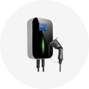
For mobile equipment such as electric vehicles or robotics, the motor control unit may be integrated directly into the motor housing or mounted nearby within the chassis. Automotive applications, especially in electric and hybrid vehicles, often place the MCU close to the drive motor under the hood or within the drivetrain assembly.
Environmental factors also influence placement. Units used outdoors or in harsh industrial settings may require protective enclosures and strategic positioning to avoid exposure to moisture, dust, vibration, or extreme temperatures.
The primary function of a motor control unit is to regulate and manage the operation of electric motors across various applications. It serves as the interface between the power source and the motor, ensuring safe, efficient, and precise control over motor behavior.
Key functions include:
- Start/Stop Control: Initiates and halts motor operation based on input signals or user commands.
- Speed Regulation: Adjusts motor speed using variable frequency drives (VFDs) or pulse-width modulation (PWM), particularly important in conveyor systems and process control.
- Direction Control: Manages forward and reverse rotation, essential in machinery requiring bidirectional movement.
- Acceleration/Deceleration: Controls the rate at which the motor speeds up or slows down to prevent mechanical stress and optimize performance.
- Protection: Monitors for overcurrent, overheating, short circuits, and other faults, triggering shutdowns when necessary to prevent damage.
- Feedback Integration: Processes signals from sensors like encoders and tachometers to maintain accurate motor control in closed-loop systems.
These functions make motor control units indispensable in industries ranging from HVAC and robotics to automotive and renewable energy systems.
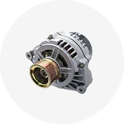
A motor control unit comprises several critical components that work together to enable precise and reliable motor management. These components can vary depending on the complexity of the system but generally include:
| Component | Description | Function |
|---|---|---|
| Control Circuits | Includes relays, contactors, programmable logic controllers (PLCs), and microprocessors | Processes input commands and manages operational logic |
| Power Circuits | Composed of power semiconductors like MOSFETs, IGBTs, and thyristors | Delivers controlled electrical power to the motor windings |
| Protective Devices | Fuses, circuit breakers, thermal overload relays, and electronic protection modules | Safeguards the motor and control unit against electrical faults |
| Input/Output Interfaces | Digital and analog inputs/outputs, communication ports (e.g., CAN, RS-485) | Enables integration with external systems and sensors |
| Cooling Systems | Heat sinks, fans, or liquid cooling mechanisms | Maintains optimal operating temperature to ensure reliability |
Advanced motor control units may also incorporate digital signal processors (DSPs) for real-time control, feedback devices for precision monitoring, and safety relays for compliance with industrial standards like ISO 13849.