All categories
Featured selections
Trade Assurance
Buyer Central
Help Center
Get the app
Become a supplier
(2992 products available)


 Ready to Ship
Motor PWM circuits come in many types, each suitable for a particular motor or application. These circuits differ in the number of phases, the type of motor, and the control method. Below is an overview.
Single-Phase PWM Circuits
These are the simplest PWM circuits. They are mainly used in small AC motors. These include universal motors and small AC induction motors. The circuits are simple to design and control. They offer basic speed control.
Dual-Phase PWM Circuits
These circuits are also called single-phase AC with two-phase excitation. They are used in motors requiring more complex control mechanisms. These are found in stepping motors and some brushless DC motors. They provide better control over speed and torque characteristics compared to single-phase systems.
3-Phase PWM Circuits
These circuits are commonly used with brushless DC motors and synchronous motors. It includes permanent magnet synchronous motors (PMSMs). The most common source of this circuit is the inverter.
They are also used in industrial applications, electric vehicles, and robotics. Here, precise control over speed, direction, and torque is essential.
High-Frequency PWM Circuits
They are used in applications involving high-speed motors. These include micro motors and certain types of turbogenerators. At this point, the PWM frequency needs to be high to enable smoother control over motor speed.
Low-Frequency PWM Circuits
These circuits are used in applications where motors operate at low speeds. These include large DC motors in electric vehicles or heavy machinery. The frequency of PWM is low.
That minimizes losses in the control system and is more efficient in low-speed torque-heavy applications.
A motor PWM circuit comprises several key components. Each of them plays a vital role in controlling the motor's operation. Below is a composition of the circuit.
Microcontroller or PWM Generator
It generates the PWM signal. This controls the motor speed and direction. The microcontroller adjusts the duty cycle based on user input or feedback from sensors. This determines the amount of power delivered to the motor.
Power Transistors or MOSFETs
These function by switching the motor on and off. They do this at the PWM frequency. Depending on the PWM signal, these devices control the amount of current reaching the motor. They help manage the heat generated during the operation.
Diodes
These protect the circuit from voltage spikes. It occurs when the motor coils are de-energized. These spikes come from the motor's inductive load. It is known as back EMF (Electromotive Force), which can damage the circuit components.
Filter Capacitors
They smooth out the PWM signal before it reaches the motor. This creates a more consistent voltage. It reduces the motor's electrical noise and helps prevent damage to sensitive components.
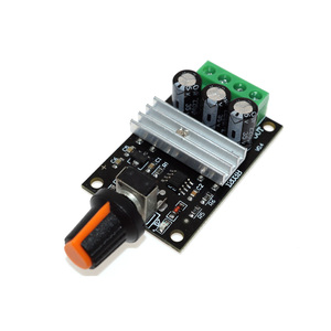
Heat Sink
At this point, due to the power transistors' continuous switching and voltage variations, they generate a lot of heat. These Helps to dissipate heat. It ensures that the components do not exceed their maximum operating temperatures, which would affect their performance.
Motor PWM circuits are widely used across various industries and applications, enabling precise control of motor performance. Below is an application of the circuits.
Electronics
They are used in controlling small DC motors in devices like hard drives, cameras, and electric toothbrushes. They provide smooth operation with variable speed and low power consumption.
Automotive Industry
In this industry, motor PWM circuits control electric windows, seat adjustments, and wiper motors, So up-and-down motors. They are vital in managing brushless DC motors in electric and hybrid vehicles' powertrains.
Industrial Automation
They control the speed and torque of AC and DC motors in conveyor belts, robotic arms, pumps, and fans. It helps in enhancing precision in manufacturing processes, thereby improving efficiency and reliability.
HVAC Systems
They control the speed of compressors and fans in heating, ventilation, and air conditioning systems. They help maintain the desired temperature and airflow, thus improving energy efficiency.
Robotics
They are used to control the movements of different motors in robotic systems. This includes servos for robotic arms or wheels for mobile robots. They enable precise control over position, speed, and torque.
Renewable Energy
They manage the power output of solar inverters and control the operation of wind turbine generators. This maximizes energy conversion and maintains grid stability.
Aerospace
In this industry, they control the actuation systems for flaps, elevators, and other trim systems. There is precise control over these movements, ensuring flight safety and performance.
Motor PWM circuits offer numerous advantages, making them a preferred choice for many applications. Below is an advantage of using these circuits.
Energy Efficiency
In normal circumstances, Motors consume less power when operated at varying speeds using PWM. This is done compared to direct voltage adjustment. The reason is that motor speed control using voltage reduction methods causes high energy losses.
Conversely, PWM limits these losses by switching the transistors efficiently. This results in less heat generation and significant energy savings, especially in battery-powered systems.
Smooth Control
The on and off of the motor control by the PWM signals help to reduce the motor speed variation. This is known as speed modulation. It results in better precision and smoother operation. This is particularly important in robotics, industrial machinery, and automotive applications requiring fine control.
Heat Dissipation
These circuits minimize heat generation. They do this by reducing power losses in the form of wasted heat. This is through efficient switching. This is a huge bonus when dealing with high-power motors. These motors are likely to damage sensitive components due to increased heat.
Directional Control
Using PWM, DC brushless motors can easily be driven in reverse. This is done by simply changing the duty cycle of the signal. This reverses the motor's direction. Such versatility makes PWM circuits very valuable in applications like robotics. These spaces need agile movements.
Speed Regulation
When a load variation occurs, the PWM circuits automatically adjust the duty cycle to maintain the desired speed. This means that the systems can resist changes in load without affecting performance. It leads to consistent operation across different scenarios.
Selecting the right motor PWM circuit depends on various factors to ensure optimal performance. Below are factors to consider.
Motor Type
The PWM circuit should be based on the motor's needs and specifications. These types are DC motors, stepper motors, and brushless AC motors. Each motor type requires a different PWM approach. This is due to the differences in their electromagnetic structures.
Control Precision
What level of control is needed over speed and torque? For example, brushless DC motors require high precision in PWM signals for smooth operation. Steppers, on the other hand, require precise duty cycle steps for accurate positioning.
Frequency Range
The frequency range of the PWM circuit should match the range of the motor. This will ensure efficient performance. Low-frequency PWM is ideal for simple DC or small AC motors. High-frequency PWM is suited for brushless motors and other high-speed applications.
Power Rating
Frequency PWM circuits are designed with various power ratings in mind. These power ratings are low-end, mid-range, and high-end.
So, the power rating of the circuit should match that of the motor to avoid under or overloading the system. Circuit overloading causes damage. Conversely, underloading leads to inefficient performance.
Heat Management
Heat dissipation is an important consideration when selecting a PWM circuit. Some circuits, especially those operating at high frequencies, can generate significant heat. This may lead to overheating.
Look for circuits with appropriate heat sinks or cooling mechanisms. This ensures overall system stability.
A1: Brushless DC motors are controlled using 3-phase PWM circuits. The microcontrollers generate three distinct PWM signals. Each signal is then fed to a power transistor.
As the transistors switch on and off, the motor windings are energized in a rotating sequence. This creates a magnetic field that interacts with the permanent magnets on the rotor. This ultimately causes the rotor to spin.
A4: Capacitors smooth out voltage ripples from PWM signals to ensure motors receive stable DC voltage. This smoothing happens by charging when voltage spikes occur and discharging during low voltage. What this does is reduce electrical noise and prevent motor damage.