All categories
Featured selections
Trade Assurance
Buyer Central
Help Center
Get the app
Become a supplier
(1399 products available)


 Ready to Ship
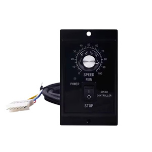
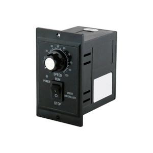
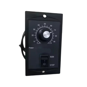
Motor speed control circuits are essential for adjusting the speed of motors in various applications. Below are the main types of motor speed control circuits.
These circuits employ methods such as:
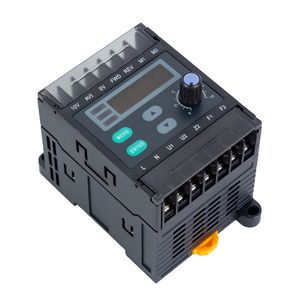
Variable Frequency Drives (VFDs)
The circuits control motor speed by adjusting the frequency of the input AC power, effectively varying the speed of an AC motor, particularly induction motors. A common application of this regulation is in industrial motors, pump automation, and fan systems. Smooth operation minimizes stress on the equipment, and energy wastage is also lessened.
Phase Control
Thermistors, TRIACs, and other semiconductor devices are used to control the phase angle of AC signal delivery to motors. This technique effectively adjusts motor speed and is frequently used in dimmer switches for lighting and speed controls for fans and universal motors.
These offer greater flexibility and ease of control because it is easier to vary the speed of DC motors than AC motors. They use four methods to maintain DC motor speed, namely:
Pulse Width Modulation (PWM)
This technique involves varying the width of voltage pulses supplied to the motor. The motor speed is directly proportional to the pulse width. PWM is energy efficient and is extensively used in electric vehicles, robotics, and precision motors.
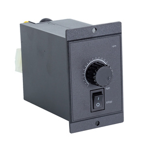
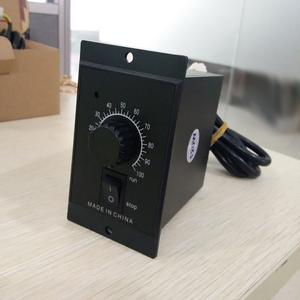
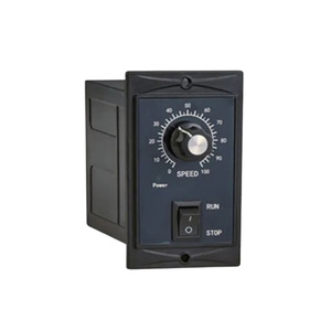
Voltage Regulation
DC motor speed can be varied by adjusting the supply voltage through resistors or variable potentiometers. This simple method can be applied to low-power applications such as fans and small pumps.
Field Weakening
This method reduces the motor's field current to increase rotor speed, even beyond its normal rated speed. Field weakening is useful in applications requiring variable speed over long ranges, such as electric vehicles and conveyor systems.
These circuits control stepper motors precisely. Controlling the steps and direction of the motor achieves accurate position control, mainly used in 3D printers, robotics, and CNC machines. The common types of circuits include:
Full-step, Half-step, Micro-stepping Control
Different driver circuits control the motor in full-step, half-step, or micro-stepping modes. Full-step and half-step drive modes provide basic position control, while micro-stepping offers smoother motions and higher resolutions. Their applications involve robotics, CNC machines, and camera platforms.
Chopper Control
Chopper controllers apply pulse with modulation to keep a constant torque under all conditions by intersecting the motor's desired current with the actual measured motor current. This control method is mainly used in applications demanding high precision and torque, such as robotics and automated machinery.
Motor speed control circuits adjust the speeds of various machine components and, thus, the motors. AC and DC motor controllers operate conveyor belts at different speeds to achieve the desired transport speed and mixing machines to attain the required substance mixing rate. Moreover, VFDs optimize motor speeds in large industrial fans and pumps, resulting in energy-efficient ventilation and fluid systems. Overall, smooth motor speed adjustments minimize equipment wear and tear and boost production efficiency.
Speed control circuits regulate compressor and fan motor speeds in heating, ventilation, and air conditioning systems. VFDs maintain optimal airflow and refrigerant pressures in large commercial HVAC systems, increasing energy efficiency and system reliability. For instance, a variable fan speed reduces energy consumption in residential air conditioners. Furthermore, speed controls reduce system noise and prevent rapid cycling of components in the system, thus prolonging their lifespan.
Electric vehicles use PWM and other two DC methods in road and rail transport to achieve desired vehicle speeds and improved energy efficiency during different driving conditions. Moreover, robotics vehicles in warehouses use these electric vehicles to move heavy loads with controlled precision. There is also a great reliance on battery-powered devices, such as electric scooters and handheld tools, for efficient speed regulation while maximizing battery life.
Stepper and servo motor control circuits in robotics allow for precise speed and position control of robotic arms, legs, and other parts. PWM helps achieve the required torque and speed for different operations, such as pick and place, assembling, or painting. Micro-stepping gives their motors smooth motions for delicate tasks, such as medical surgeries or electronic component assembly. In automation, AC motor controllers drive linear actuators, lifts, and other equipment used in transporting goods in dynamic warehousing and fulfillment centers.
In renewable energy systems, speed control circuits optimize generator and pump operation. DC motor controllers help maintain the battery charge within electric grids at the desired level, depending on the battery state of charge and electric grid needs. VFDs on wind turbine generators adjust rotor speeds according to wind speed to prevent generator damage and achieve optimal energy production. In hydroelectric systems, pump frequency controllers regulate water flow and variation in production electrical generation.
These circuits have different requirements, depending on the application. For instance, PWM controllers must switch the current to a motor with a high frequency to ensure smooth operation. The frequency will depend on the motor and application, but generally, it is in the range of a few kilohertz to several tens of kilohertz. Chopper control circuits also come with current sensing and feedback components that require PWM controllers to maintain motor current at desired levels to avoid motor damage due to overloading or under-amping.
Resistors
In DC motor speed control circuits, a resistor is used to give motor speed control by varying the supply voltage, thus helping maintain the desired motor speed regardless of load changes. In a chopper control circuit, the resistor is used with the current.
Semiconductors
Semiconductors like diodes and thyristors are operational in DC and AC motor speed control circuits. For example, thyristors control the current applied to the motor in the chopper control circuit to avoid back EMF.
Field Coils
These are applied in DC electromagnet motors to create magnetic fields that help position and speed control. The applied voltage influences the field coil current, thus adjusting motor speed. Cutting back the field coil current reduces the motor's speed, while increasing the current boosts the motor's torque.
Triacs & Thermistors
A TRIAC is a thyristor device that can control AC load by enabling and disabling current flow. It can switch and even regulate power in motor speed control circuits. Usually, a thermistor is a semiconductor whose resistance varies with temperature. It acts as a temperature sensor or an electrical element in an electrical circuit to provide speed control or motor protection against overheating in industrial applications.
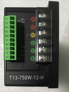
Installation
One of the major considerations when installing motor speed control circuits involves the type of motor being employed. For instance, PWM controls work well in DC motors, while VFD works for AC motors. The controlling circuit needs to be connected to the power supply and motor properly to avoid electrical hazards and equipment damage. Current and voltage sensors are typically installed to monitor motor performance and feedback control systems. The circuit should then be enclosed in a protection casing against dust, moisture, and other environmental elements, as well as overheating.
Operation
The motor speed regulation circuit normally receives input from external devices, such as sensors or user interfaces. The DC-speed control circuits help users set the desired speed. The sensors collect motor parameters, which are then sent to the circuit processing unit for speed adjustment. This feedback loop ensures motor speeds remain close to set targets even under load changing conditions.
Motor speed control circuits can be protected from water and dust damage. Their housings are usually rated IP65 or higher, signifying dust-tight and water-resistant protection. This rugged design is crucial for outdoor and industrial applications where environmental exposure may hinder circuit functionality. Sealing and protective coatings on the casing for internal components further enhance durability against water and dust.
Overheating can cause damage to the electronic components of these circuits. Effective heat dissipation mechanisms, such as heat sinks or cooling fans, are incorporated into the design to counter this. These are mounted on the circuit to absorb and dissipate heat away from critical components, ensuring the circuit operates within safe temperature limits even under heavy loads. Besides, thermal sensors connected to the feedback control system shut down the motor when overheating occurs to prevent circuit failure.
Every motor control circuit features safeguard mechanisms against excessive loads that may damage the motor and surrounding components. These overload protection methods include current sensing that shuts off the circuit once motor draws excess current, thereby preventing overheating and potential burn-out. Torque limits are also employed in DC and AC circuits, where motor stall conditions generate an excessive torque, thus protecting mechanical systems from failure.
Motor control circuits often operate in electrically dynamic environments, exposing them to the possibility of electrical surges and short circuits. Circuit breakers, fuses, and surge protectors are integrated into these circuits to mitigate this risk. For example, a fuse acts as an electrical protector that easily blows to prevent excess current from reaching the motor and damaging the circuitry.
Switching regulators and PWM motors generate high-frequency switching noise that can interfere with nearby electronic devices. Proper circuit layout, filtering, and shielding techniques are used to minimize EMI emissions. It is possible to reduce radiated emissions by enclosing sensitive components and grounding their shields. This ensures smooth motor operation and does not disrupt signals in nearby equipment.
A1. Some of the factors to consider include the motor type, operational requirements such as load, speed and torque, and the environmental conditions under which these circuits will be operating. Moreover, expected efficiency and cost are considered.
A2. Some of the common problems include overheating due to electrical or mechanical overload, which may lead to motor failures and damage to the system. Electronic components like tri-circuits, thermistors, and others face circuit failures due to power surges and insufficient voltage regulation.
A3. These circuits have low maintenance requirements. The protectors, such as surge protectors, TH, dust, debris, and other external elements, need to be cleaned regularly. Also, the internal components, like semiconductors, should be checked for signs of wear or damage due to overheating.
A4. Yes, they are eco-friendly. These circuits make electrical motors operate efficiently, thus minimizing energy consumption. Furthermore, smooth motor operations lower mechanical wear and tear on industrial systems, which leads to reduced emissions.
A5. Yes, these circuits are widely used across many modern industries that require motion control of electromechanical systems, such as manufacturing, transportation, robotics, and HVAC.