


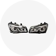


How to DIY and Replace VW Beetle Headlight Switch
Replacing the headlight switch on a Volkswagen Beetle is a straightforward yet essential maintenance task that every Beetle owner should consider handling independently. This guide will walk you through the entire process, ensuring both safety and efficiency while providing insights into best practices and common pitfalls to avoid.
Safety First: Always disconnect the battery before beginning any electrical work to prevent shocks or short circuits. Work in a dry, well-lit environment and keep tools organized to avoid accidents.
Gathering Tools and Materials
Before starting the replacement process, ensure you have all the necessary tools and parts ready. Having everything prepared will streamline the workflow and reduce interruptions.
- Flat-head screwdriver – for gently prying off trim pieces
- Phillips screwdriver – for removing screws securing the switch
- Trim removal tool (optional but recommended) – to safely remove interior panels without scratching surfaces
- VW Beetle-compatible headlight switch – confirm compatibility with your specific model year and configuration
- Camera or smartphone – to photograph wiring connections for reference
Step-by-Step Replacement Procedure
- Disconnect the Battery
Begin by turning off the ignition and removing the key. Locate the negative terminal on your car’s battery and use a wrench to loosen the nut. Carefully disconnect the cable and secure it away from the terminal to prevent accidental contact during the procedure.
- Remove Interior Trim Panels
The headlight switch is typically located on the dashboard or steering column. Carefully remove any surrounding trim panels using a trim removal tool or flat-head screwdriver. Apply gentle pressure to avoid cracking plastic components. If resistance is encountered, check for hidden clips or screws that may need removal first.
- Access and Remove the Old Switch
Once the trim is removed, locate the headlight switch. Use a Phillips screwdriver to remove the mounting screws securing the switch to the dashboard. Gently pull the switch forward until the electrical connectors become visible. Before disconnecting them, take a photo of the wiring layout or note down which connector goes where to avoid confusion later.
- Disconnect Electrical Connectors
Press the locking tabs (if present) and carefully unplug each connector from the old switch. Avoid pulling on the wires themselves—grab the connector housing instead to prevent damage. Set the old switch aside in a safe place until the new one is installed.
- Install the New Headlight Switch
Take the new switch and reconnect the electrical connectors following your notes or photos. Ensure each connection clicks securely into place. Once all connectors are attached, carefully slide the switch back into its housing and align it properly. Secure it with the original screws, tightening them just enough to hold the switch firmly without stripping the threads.
- Reinstall Trim Panels
Replace the trim panels you previously removed. Make sure all clips are fully engaged and that the panels sit flush against the dashboard. Avoid forcing any piece—if something doesn’t fit easily, double-check alignment or missing fasteners.
- Reconnect the Battery and Test
Reattach the negative battery cable and tighten the nut securely. Turn the ignition key to the “on” position and test the headlight switch. Cycle through all settings (parking lights, headlights, high beams) to verify proper operation. If the lights do not turn on or flicker intermittently, double-check your wiring connections and ensure they are seated correctly.
| Stage | Critical Actions | Potential Issues | Tools & Parts Needed |
|---|---|---|---|
| Preparation | Verify part compatibility, gather tools, document wiring | Mismatched switch, missing tools, unclear wiring references | Replacement switch, screwdrivers, camera |
| Disassembly | Properly remove trim and access the switch | Broken clips, damaged trim, misaligned components | Trim removal tool, Phillips screwdriver |
| Installation | Secure connections, correct switch positioning | Loose wiring, improper seating, stripped screws | New switch, screwdrivers |
| Testing | Verify all functions post-installation | Incomplete installation, intermittent lighting | Battery, multimeter (optional) |
DIY Tip: If your Beetle has additional features like fog lights or automatic headlamps, consult the wiring diagram specific to your model. Some switches come with labeled diagrams on the casing itself—use these as a visual aid during reconnection.
Troubleshooting Common Problems After Installation
If the headlight switch does not function correctly after installation, here are some common issues and solutions:
- Lights Won't Turn On: Double-check that all electrical connectors are properly connected and secured. Also, verify that the battery is fully connected and charged.
- Flickering Lights: A loose ground wire or poor connection can cause this issue. Recheck all wiring points and ensure they’re snug.
- Only One Setting Works: The switch may be defective or incorrectly wired. Cross-reference the wiring diagram again and confirm the new switch is compatible with your vehicle's system.
By following this comprehensive guide, replacing the headlight switch on your VW Beetle becomes a simple, rewarding DIY project. With attention to detail and careful execution, you'll restore full functionality to your vehicle's lighting system while gaining valuable hands-on experience.
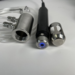
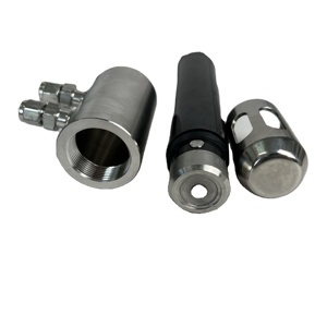
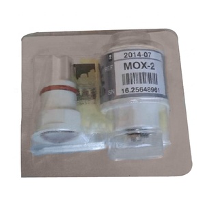
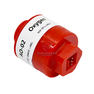
Specifications and Maintenance of Oxygen Sensors
Key Technical Specifications
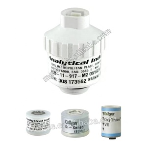
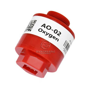
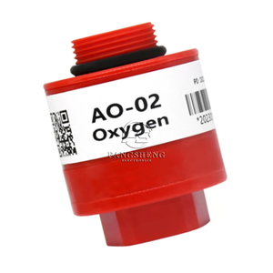
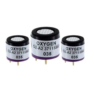
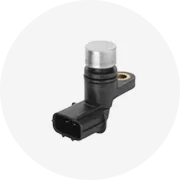
Oxygen sensors (also known as lambda sensors) play a crucial role in modern vehicle emissions control systems by measuring the amount of oxygen in exhaust gases. Their specifications vary based on type, vehicle make, model, and year of manufacture. Understanding these specifications helps ensure optimal engine performance, fuel efficiency, and compliance with emission standards.
Voltage Output Range
The standard voltage output for most zirconia-based oxygen sensors ranges between 0.1V and 0.9V. This analog signal is interpreted by the Engine Control Unit (ECU) to determine whether the air-fuel mixture is running rich or lean.
A reading below 0.45V typically indicates a lean mixture (excess oxygen), while values above 0.45V suggest a rich mixture (insufficient oxygen). The ECU uses this data to adjust fuel injection timing and volume accordingly.
Response Time
Modern oxygen sensors have an average response time of approximately 100 milliseconds. This rapid reaction allows the ECU to maintain real-time adjustments to the air-fuel ratio during dynamic driving conditions.
Sensors with slower response times can lead to inefficient combustion, increased emissions, and reduced fuel economy. Wideband oxygen sensors often provide faster and more precise readings than traditional narrowband types.
Operating Temperature Range
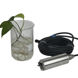
Oxygen sensors must function within extreme temperatures, typically ranging from 300°C to 800°C. These high temperatures are necessary for accurate oxygen detection and sensor activation.
Sensors located closer to the engine (upstream sensors) experience higher thermal stress compared to downstream sensors. Most modern sensors include internal heating elements to reach operational temperature quickly, especially during cold starts.
Durability and Lifespan
While many oxygen sensors are rated for up to 100,000 miles of operation, their actual lifespan depends on driving conditions, fuel quality, and engine maintenance practices.
Exposure to oil or coolant leaks, frequent short trips, and poor fuel combustion can significantly reduce sensor longevity. Heated oxygen sensors generally last longer due to better thermal management and faster warm-up times.
| Specification | Description | Typical Value/Range |
|---|---|---|
| Signal Voltage | Output range used by ECU for air-fuel adjustment | 0.1V - 0.9V |
| Response Time | Time taken to detect changes in oxygen levels | ~100 milliseconds |
| Operating Temp | Minimum temp required for accurate readings | 300°C - 800°C |
| Lifespan | Expected service life under normal conditions | Up to 100,000 miles |
| Heater Circuit | Internal heating element power rating | 2-4 amps at 12V |
Recommended Maintenance Practices
To ensure consistent performance and extend the operational life of oxygen sensors, regular maintenance is essential. Here are key practices that contribute to long-term reliability:
Important: If one oxygen sensor shows signs of failure or triggers a fault code, it's advisable to inspect all sensors in the system. Replacing only one sensor in a multi-sensor setup can create calibration mismatches, affecting engine tuning and emissions performance.
How to Choose VW Beetle Cylinder Heads
Selecting the right cylinder heads for Volkswagen Beetle engines is a critical decision for business buyers who supply parts to mechanics, restorers, and performance enthusiasts. The correct VW Beetle head cylinders ensure optimal engine function, longevity, and compatibility with specific model years and engine types.
Engine Compatibility
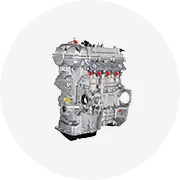
VW Beetles were produced over several decades and featured various engine configurations, particularly air-cooled flat-four engines ranging from 1200cc to 1600cc. Buyers must verify that the cylinder heads match the exact engine displacement and year of manufacture to avoid fitment issues or performance degradation.
- Early models (pre-1966) used smaller combustion chambers and different valve angles
- Late-model Beetles may require larger ports and modernized cooling fins
- Ensure compatibility with carburetion systems and ignition setups
Key consideration: Cross-reference part numbers and engine codes (e.g., Type 1, Type 3) before purchasing in bulk
Material Composition
Cylinder heads endure extreme heat and pressure within the engine, making material choice crucial for reliability and performance. VW Beetle head cylinders are commonly made from either cast iron or aluminum alloys, each offering distinct advantages depending on the application.
- Cast Iron: Durable and resistant to warping under high temperatures but heavier and less efficient at dissipating heat
- Aluminum Alloys: Lightweight with superior thermal conductivity, ideal for performance builds and street use
- Hybrid Options: Some aftermarket suppliers offer composite designs combining strength and weight savings
Expert tip: Aluminum heads are preferred for modified engines aiming for increased horsepower and better cooling efficiency
Quality and Manufacturer Reputation
The quality of VW Beetle head cylinders can vary significantly between OEM (Original Equipment Manufacturer) and aftermarket suppliers. Business buyers should prioritize reputable brands that maintain strict manufacturing standards to ensure consistent performance and longevity.
- OEM parts (like those from Volkswagen AG or licensed suppliers) guarantee factory-level precision and fitment
- Aftermarket options offer cost-effective alternatives but vary in quality—look for ISO-certified manufacturers
- Verify if the supplier provides documentation like material specs and testing reports
Quality assurance: Request samples or certifications when sourcing from new vendors
Performance Modifications
For customers interested in enhancing engine output, modified VW Beetle head cylinders can provide significant performance gains. These modifications include combustion chamber reshaping, port polishing, and oversized valve installation to improve airflow and combustion efficiency.
- Ported and polished heads increase airflow velocity and volume
- Enlarged combustion chambers optimize compression ratios
- Custom CNC-machined heads tailored to specific engine builds
- Some suppliers offer bolt-on kits for easy upgrades
Business opportunity: Partner with shops offering modification services to expand your product value proposition
Cooling System Design
The majority of VW Beetle engines are air-cooled, which directly influences the design and features of compatible cylinder heads. Proper cooling fin geometry, airflow channels, and baffle placements are essential to prevent overheating and ensure reliable operation.
- Air-cooled heads feature prominent cooling fins and baffles for optimal airflow
- Water-cooled conversions require specially designed heads with coolant passages
- Ensure heads align properly with shroud and fan assemblies for effective cooling
Critical check: Confirm that replacement heads retain original cooling system compatibility
Warranty and Support
Offering VW Beetle head cylinders with comprehensive warranties adds value for end users and reduces return risks for business buyers. Warranties also reflect the manufacturer's confidence in their product’s durability and performance.
- Look for minimum 1-year warranty terms
- Check return policies and availability of technical support
- Preferred suppliers offer RMA (Return Merchandise Authorization) processes
Smart strategy: Prioritize products with clear warranty documentation and responsive customer service
Purchasing Advice: For general retail and repair shops, stock a mix of OEM-quality and high-grade aftermarket VW Beetle head cylinders. This allows you to cater to both restoration purists and budget-conscious consumers while maintaining profitability. Always request technical datasheets and fitment guides from suppliers to assist your customers accurately.
| Use Case | Recommended Material | Design Features | Best For |
|---|---|---|---|
| Stock Restoration | Cast Iron | Factory specifications, standard cooling fins | Museum pieces, classic shows |
| Daily Driver Upgrade | Aluminum Alloy | Improved cooling, lightweight | Commuter vehicles, mild tuning |
| Performance Build | Modified Aluminum | Ported/polished chambers, oversized valves | Racing, hot rods, enthusiast builds |
| Water-Cooled Conversion | Hybrid Cast Iron/Aluminum | Coolant passages, hybrid mounting | Modernization projects |
DIY Guide to Replacing an Oxygen Sensor
Replacing an oxygen sensor is a straightforward yet crucial maintenance task that can significantly improve your vehicle’s fuel efficiency and emissions performance. This comprehensive guide walks you through the process of replacing an oxygen sensor with basic tools, ensuring a safe and effective repair.
Safety Reminder: Always work on a cool engine to avoid burns from hot exhaust components. Disconnecting the battery before starting any electrical work is also recommended to prevent short circuits or damage to the ECU (Engine Control Unit).
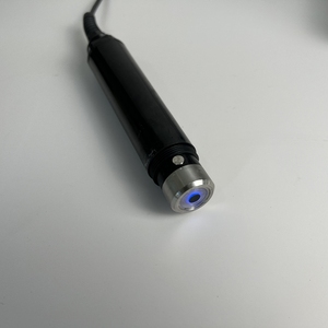
Understanding the Oxygen Sensor's Role
The oxygen sensor measures the amount of unburned oxygen in the exhaust gases and sends this data to the vehicle's computer (ECU). Based on this information, the ECU adjusts the air-fuel mixture for optimal combustion. A faulty sensor can lead to poor fuel economy, increased emissions, rough idling, and even trigger the check engine light.
Tools and Materials Needed
- New Oxygen Sensor – Ensure it's compatible with your vehicle make and model
- Socket Wrench – For general bolt removal
- Oxygen Sensor Socket – Specifically designed to grip the sensor without damaging it
- Torque Wrench – To ensure proper tightening per manufacturer specs
- Anti-Seize Compound (Optional) – Helps prevent corrosion and seizing for easier future replacement
- Gloves and Safety Goggles – For protection against sharp edges and debris
Step-by-Step Replacement Process
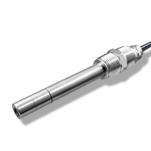
- Locate the Oxygen Sensor
Oxygen sensors are typically found in the exhaust manifold or along the exhaust pipe, either before (upstream) or after (downstream) the catalytic converter. Consult your vehicle’s service manual if you're unsure of its location.
- Disconnect the Electrical Connector
Carefully press down on the locking tab (if present) and gently pull the connector away from the sensor. If it resists, try wiggling it slightly while pulling straight back. Avoid pulling on the wires themselves to prevent damage.
- Remove the Old Oxygen Sensor
Fit the oxygen sensor socket over the sensor and use a socket wrench or breaker bar to loosen it. Be cautious not to apply too much force, which could damage surrounding components. Once loose, unscrew it by hand if possible.
- Apply Anti-Seize Compound (Optional)
If your new sensor does not come pre-lubricated, apply a thin layer of anti-seize compound to the threads. Do not apply it to the sensing area at the tip of the sensor, as contamination could affect its accuracy.
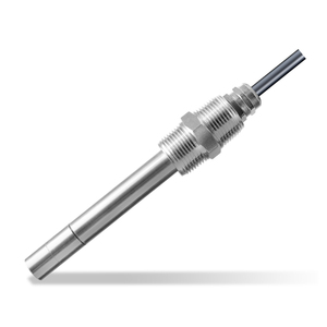
- Install the New Oxygen Sensor
Screw the new sensor into place by hand initially to avoid cross-threading. Once started, use a torque wrench to tighten it according to the manufacturer's specifications—typically around 30 ft-lbs unless otherwise stated.
- Reconnect the Electrical Connector
Align the connector with the sensor and push it firmly until you hear a click, indicating it has locked into place. Double-check that there are no loose connections or exposed wires.
- Start the Engine and Check for Leaks
Start the engine and let it idle while inspecting the sensor area for signs of exhaust leaks, such as hissing sounds or visible smoke. If everything appears normal, clear any error codes using an OBD-II scanner if necessary.
| Phase | Key Actions | Potential Issues | Recommended Tools |
|---|---|---|---|
| Preparation | Verify sensor compatibility, gather tools | Mismatched sensor type, missing specialized socket | VIN lookup tool, vehicle manual |
| Removal | Label wiring, remove old sensor carefully | Broken connector clips, damaged threads | Oxygen sensor socket, pliers |
| Installation | Hand-tighten first, then torque properly | Cross-threading, incorrect torque | Torque wrench, gloves |
| Testing | Check for leaks, scan for codes | Unresolved DTCs, exhaust leaks | OBD-II scanner, flashlight |
Pro Tip: If your check engine light was on due to a faulty oxygen sensor, reset it after installation using an OBD-II code reader. Some vehicles may require driving several miles before the system recalibrates fully.
Post-Replacement Tips
- Monitor your vehicle’s performance for a few days after replacement to ensure the sensor is functioning correctly.
- Keep the old sensor as a temporary backup in case of emergencies, but remember it may be less accurate over time.
- Periodically inspect all exhaust components during routine maintenance to catch issues early.
Frequently Asked Questions About Oxygen Sensors
A vehicle may start and run temporarily without a functioning oxygen sensor, but it will not operate efficiently or safely. The oxygen sensor is integral to the engine's fuel management system, providing real-time feedback to the Engine Control Unit (ECU) about the amount of oxygen present in the exhaust gases. This data allows the ECU to adjust the air-fuel mixture for optimal combustion.
Without this critical input, the ECU defaults to pre-programmed values that do not adapt to changing conditions, which can lead to:
- Poor fuel economy – The engine may run too rich (too much fuel) or too lean (not enough fuel).
- Increased emissions – Improper combustion results in higher levels of harmful pollutants being released.
- Engine performance issues – Symptoms like rough idling, stalling, hesitation, or reduced power may occur.
- Catalytic converter damage – A faulty air-fuel ratio can cause overheating and eventual failure of this expensive component.
Bypassing or removing the oxygen sensor is not advisable and often illegal due to environmental regulations. For proper vehicle function and compliance, always ensure the oxygen sensor is working correctly.
Oxygen sensors are designed to last many years, but they can degrade over time due to exposure to extreme heat, contaminants, or simply age. Recognizing the signs of a failing oxygen sensor early can help maintain your vehicle’s performance and efficiency. Common symptoms include:
- Check Engine Light (CEL) – One of the most common indicators; diagnostic trouble codes related to the oxygen sensor (e.g., P0135, P0141) may be stored.
- Decreased fuel efficiency – If the ECU cannot accurately adjust the fuel mixture, more fuel may be consumed than necessary.
- Rough idle or misfires – An incorrect air-fuel ratio can cause unstable engine operation at idle or under light load.
- Failed emissions test – High levels of hydrocarbons or carbon monoxide in the exhaust can result from a malfunctioning sensor.
- Hesitation during acceleration – Delayed throttle response or jerky performance may indicate a problem with air-fuel regulation.
- Black smoke from the exhaust – A sign of running too rich, which could stem from a faulty sensor reading.
If you notice any of these symptoms, it’s recommended to have a qualified technician perform a diagnostic scan and test the oxygen sensors using appropriate tools. Replacement is typically straightforward and cost-effective compared to potential engine damage caused by neglecting the issue.
While both types of oxygen sensors serve the purpose of measuring oxygen content in the exhaust gases, they differ significantly in functionality, precision, and application:
| Feature | Standard Oxygen Sensor | Wideband Oxygen Sensor |
|---|---|---|
| Type | Narrowband (Switching Type) | Wideband (Air-Fuel Ratio Sensor) |
| Measurement Range | Limited to around stoichiometric ratio (14.7:1) | Measures a broad range (from 10:1 to 20:1 air-fuel ratios) |
| Signal Output | Voltage signal (0.1–0.9V), switching between high and low | Linear current output proportional to actual air-fuel ratio |
| Precision | Less precise; only indicates lean or rich condition | Highly accurate; provides exact air-fuel ratio |
| Use Case | Basic emissions control and fuel trim adjustment | Performance tuning, advanced engine management systems |
| Cost | Lower | Higher |
The wideband oxygen sensor offers superior accuracy and responsiveness, making it ideal for vehicles with advanced engine control systems or those undergoing performance modifications. Standard sensors remain sufficient for basic emissions compliance in everyday vehicles.
Oxygen sensors are sealed units made of sensitive ceramic materials and are not designed to be repaired once they fail. Unlike some mechanical components, there are no user-serviceable parts inside an oxygen sensor. Attempting to clean or repair a faulty sensor is generally ineffective and can introduce new problems such as inaccurate readings or short circuits.
Common causes of oxygen sensor failure include:
- Contamination – From oil ash, coolant, or silicone-based sealants.
- Excessive heat – Especially near the exhaust manifold where temperatures are highest.
- Physical damage – Cracks or breakage from road debris or improper handling during maintenance.
- Electrical issues – Corroded connectors or wiring faults.
If testing confirms that the oxygen sensor is faulty, replacement is the only viable solution. It’s important to use OEM-quality or equivalent aftermarket replacements to ensure compatibility and long-term reliability.
Modern vehicles with internal combustion engines are required by law in most countries to have at least one oxygen sensor as part of their emissions control system. However, the number and placement of oxygen sensors vary depending on the vehicle's make, model, and engine configuration:
- Pre-1980s vehicles – Many older vehicles did not have oxygen sensors because electronic fuel injection and emission controls were less advanced.
- Post-1980s vehicles – Most began incorporating oxygen sensors to meet increasingly strict emissions standards.
- Dual exhaust systems – May have two upstream and two downstream sensors.
- Modern vehicles – Often feature multiple oxygen sensors (typically two to four) to monitor both pre- and post-catalytic converter exhaust composition.
The primary purpose of these sensors is to enable closed-loop fuel control, allowing the ECU to fine-tune the air-fuel mixture for maximum efficiency and minimal emissions. Therefore, while not every vehicle ever built has an oxygen sensor, virtually all modern ones do, and they play a crucial role in engine performance and environmental compliance.