All categories
Featured selections
Trade Assurance
Buyer Central
Help Center
Get the app
Become a supplier
(14624 products available)


 Ready to Ship


There are several types of motor speed controllers. Each type is designed for a different operation and motor.
Analog PID Speed Controllers
The analog controllers operate with continuous electrical signals. They adjust the motor speed based on the error signal between the desired and current speed. These controllers often use operational amplifiers and analog circuits. They are used to maintain motor speed with precision. They are mainly for systems with simple speed control requirements. They have been largely replaced by digital controllers in more complex applications.
Digital PID Motor Controllers
These controllers use digital signals. They employ microcontrollers or DSPs to compute the PID parameters. This offers the advantage of more complex calculations. This is especially true for rapid sampling. Digital PID controllers are favored in applications requiring fine-tuned speed adjustments. They provide more adaptability and precision over a wide range of operating conditions.
Software-Based PID Controllers
These are implemented through computer programs. They run on PCs or embedded systems. These kinds of Controller come into play where high-level computation and simulation are needed. They provide a platform for real-time adjustments and monitoring. They also enable the use of advanced algorithms.
Hybrid PID Controllers
These controllers combine analog and digital elements. They take advantage of the precision of digital computing and the responsiveness of analog circuits. They are effective in environments where quick adjustments are crucial. Hybrid controllers are useful in industrial settings where reliability and precision are both necessary. They easily integrate into existing systems.
Adaptive PID Controllers
These controllers adjust their PID parameters based on changing conditions. They are ideal for applications where load and speed vary frequently. Adaptive PID controllers ensure consistent performance even under fluctuating conditions. This makes them vital for dynamic control systems.
The PID controllers are widely used across various industries. This is due to their precision and reliability in maintaining motor speed.
Manufacturing Industry
They are used in industrial motors for driving machines and conveyors. They ensure that processes occur at the right speed. This helps to increase efficiency. PID controllers are employed in CNC machines for precise control. They ensure accurate cutting and shaping of materials. They help maintain the quality of the products.
Robotics
The controllers are used to control robot joints and drive systems. They help achieve smooth and precise movements. PID controllers are crucial in robotic arms for materials handling and assembly. They help them give accurate and responsive motion. This makes them an important part of robotics in manufacturing and service applications.
Automotive Industry
The controllers are commonly used in electric and hybrid vehicles. They ensure that the vehicle speed remains steady with changes in terrain or load. They help to enhance energy efficiency and driving comfort. They also find applications in servo motors. They help maintain precision in steering and braking systems.
Aerospace Industry
PID controllers are used in aircraft systems for controlling the speed of fans and pumps. They help keep essential systems operating reliably. They help maintain the speed of fuel pumps and hydraulic motors in the aircraft. This ensures that vital operations continue uninterrupted even under varying conditions.
Process Control in Chemical Plants
The controllers in this industry maintain the speeds of motors and pumps. They help regulate the movement of chemicals and materials. PID controllers are used to control mixing, pumping, and other critical processes. They help to avoid any inconsistencies that might bring about disastrous results.
HVAC Systems
The controllers are used in the fans, pumps, and compressors within heating, ventilation, and air conditioning systems. They maintain optimal air and fluid velocities. They help ensure a comfortable and consistent indoor environment. They also help to enhance energy efficiency.
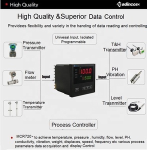
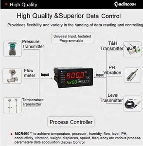
Sensors
PID motor speed control requires feedback devices to give the current speed of the motor. Common sensors used are encoders, tachometers, and speed sensors. They provide precise speed data. This is crucial for the PID controller to compare desired and actual speeds and maintain accuracy.
Controllers
The PID controllers utilize three basic operations. These three are proportional, integral, and derivative. The three together analyze the error and adjust the motor input to minimize it. Proportional reduces the error, integral eliminates past errors, and derivative predicts future errors. This gives smooth and responsive motor control.
Control Algorithms
The PID control algorithms are tuned to optimize motor performance. Different applications require different P, I, and D value combinations. They are adjusted based on the specific needs of the application to achieve optimal performance. There exist various tuning methods for these algorithms. They range from manual adjustment to automated processes using software tools.
Output Devices
In order to implement the controlling signals, speed control systems utilize various output devices like servos, motors, and drives. The output devices respond to the PID signals by adjusting motor speeds. This harmonizes with the desired setpoints. The choice of motor depends on the application.
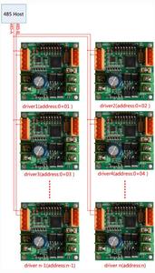
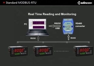
Communication Interfaces
These interfaces allow the controllers to communicate with other systems. They ensure seamless integration into larger automation frameworks. Common communication protocols for the motor speed controllers include Modbus, RS-485, and CANopen. They help the controllers exchange data and be able to synchronize with other elements.
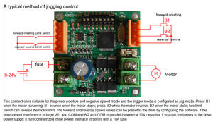
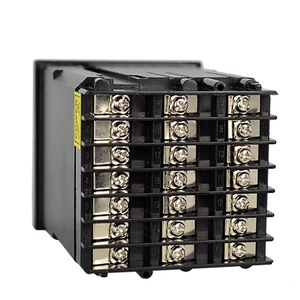
Mount the Controller to the Surface
First, mount the PID motor speed controller on a surface. Ensure that the surface is stable and has enough room for other components. This also allows easy access to the controller's connections. The mounting method depends on the controller design. One can use screws, brackets, or simply secure it with adhesive.
Connect Power Supply Wires
After securing the controller, connect it to the power supply of choice. Ensure that the voltage and current ratings of the power supply match those of the controller. Connecting the power supply has to be done carefully to avoid any electrical shocks or accidents. The positive and negative power wires should be connected to their corresponding terminals.
Connect the Motor
The next step is to connect the motor to the controller. The motor wires should be connected to the output terminals of the controller. This allows the controller to adjust the motor speed. Make sure that the connections are secure and there is no loose wiring around.
Connect Feedback Devices
Feedback devices help give real-time data on the motor speed to the controller. These devices like encoders and optical sensors need to be connected to the appropriate inputs on the controller. The connections should be done tightly to prevent any signal interference.
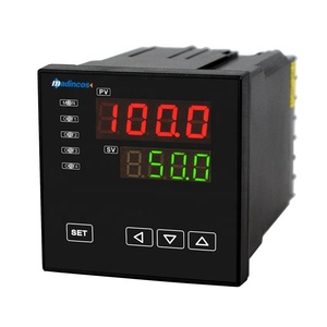
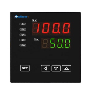
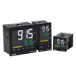
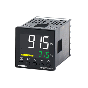
Install the User Interface Components
If the PID controller has a user interface, mount it in a convenient location. It will allow users to adjust control parameters easily. Upon completing the installation, conduct proper testing. Ensure that the motor responds correctly to control inputs. Verify that the feedback loop is functioning properly and maintains the desired motor speed.
Parameter Setting
Set the PID values of the motor speed control to the required values. Set the proportional value (P) to control the reaction to the current error. Set the integral value (I) to eliminate the steady-state error. Finally, set the derivative value (D) to predict the future error. Doing this helps ensure the system is stable and reaches the desired speed quickly.
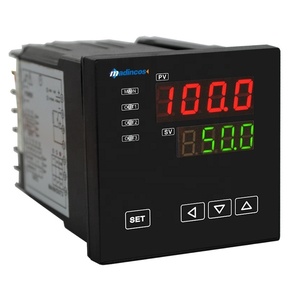
Power On
Switch the power on for the controller and the motor. Allow them to initialize properly. Ensure the display interface shows the correct readings to verify that the components are working as they are supposed to. This also helps in monitoring the parameters.
Input Speed
Put the desired speed value into the PID motor speed control. This will give a reference point for the controller to maintain. The controller will compare the input speed to the actual motor speed. It will adjust the motor to decrease the disparity between the two.
Monitoring
Continuously check the system to ensure that the motor speed remains at the desired setpoint. Observe PID graph and readings. This gives real-time data on how the motor is operating. They will show if corrections need to be made.
Adjustments
The PID values should be adjusted if they are perceived to be off. Fine-tune the parameters to improve response and reduce any possible steady-state errors. This also helps in optimizing system performance. The motor should now operate smoothly and accurately at the desired speed. All the while it responds correctly to any changes in load or external conditions.
Feedback Loop Accuracy
This means that the controllers have precise speed measurements. The accuracy of these measurements directly impacts the controller's ability to minimize errors. High-quality sensors ensure the feedback loop provides real-time data. This helps the controller make quick and accurate adjustments. They also help maintain optimal speed and torque. They also prevent overshoot or unstable operations.
Material Durability
The motor speed controls require robust and reliable material construction. Controllers made from quality materials ensure longevity in both extreme operating conditions and high loads. This reduces wear and tear and ultimately improves performance. Using durable materials like aluminum and stainless steel housings protects internal components. This enhances the overall durability of the controller.
Heat Dissipation
PID controllers manage the speed of motors by adjusting power inputs. This generates heat within the controller. Quality controllers have effective heat sinks and dissipation mechanisms. They prevent overheating and ensure system stability. Overheating can lead to system failure. Durable controllers manage heat effectively, ensuring consistent performance even in long operational hours.
Water Resistance Ratings
Many applications that use these controllers are in harsh environments with water exposure. Harsh elements like dust, water, and debris negatively affect the controller's performance. Quality controllers come with sealed enclosures and water resistance ratings. They keep internal components protected. This proves very vital in outdoor or industrial applications.
Tuning Precision
The accuracy of parameter settings (P, I, D) determines control performance. Quality controllers have automatic tuning methods to ensure optimal parameter adjustment. It reduces manual errors while enhancing smooth operations. There will be no overshoot or oscillations. This guarantees the motor works optimally without safety hazards.
Electrical Insulation
The PID motor speed control has to feature proper electrical insulation. This helps to avoid short circuits and electrical shocks. It also ensures that the components are well insulated from each other. Over time, electrical leakage can occur. Replace or regularly maintain controllers to keep proper insulation and avoid safety hazards.
Grounding
Grounding eliminates hazardous voltages. It helps ensure that all metal parts of the PID controller are properly grounded. This provides a path for any fault currents to dissipate safely. It will help reduce the risk of electrical shock to the users and damage to the motor. Ensure that grounding is done correctly and checked frequently.
Overcurrent Protection
Overcurrent can damage electrical components and pose safety risks. It is important to install protection devices such as circuit breakers and fuses. These devices will protect the controller from overcurrent conditions. They will automatically interrupt the flow of electricity in the event of an overload. This prevents any electrical hazards.
Regular Maintenance
Regular maintenance will identify potential hazards before they become risky. It will also help ensure that all components are functioning as they should. Regularly inspect the wiring to check for any signs of wear. Give frequent checks on grounding systems and overcurrent protection devices. They are crucial for maintaining a safe PID motor speed control.
Operating Conditions Monitoring
Closely monitor the operational environment to avoid any extreme conditions. Extreme temperatures, moisture, and heavy vibrations can cause electrical hazards. Use proper seals, covers, and heat sinks to protect the controller from these elements. All seals should be frequently checked for continuity and effectiveness.
A1. These controllers are used to control motor speeds. They adjust the power supplied to the motor based on the difference between the desired speed and the actual speed. They continuously calculate three terms: proportional, integral, and derivative. This gives them the name PID. They do this to minimize the error and maintain a steady motor speed even in the face of changing loads or resistance.
A2. It operates by continually measuring the motor's speed and comparing it to the desired speed. Then, it computes an error value. The controller then applies the PID formula to this error. It produces an output that adjusts the motor's power supply. This brings the motor speed in line with the desired setpoint.
A3. Proper tuning of the PID parameters is key to optimal controller performance. It will help minimize the error efficiently without oscillating too much or taking a long time to reach the setpoint. Manual tuning helps adjust the controller to respond quickly without overshooting. It will slow the controller down if set too high. Then, after doing so, users will have smooth and stable motor operations.
A4. The essential elements of this system are the controller, error sensor, and actuator. The controller computes the necessary adjustments based on the error. The sensors measure the motor speed. Actuators are then put in place to adjust the motor power. These three work together to maintain the desired motor speed.
A5. The longevity of this controller largely depends on the conditions it operates in. Those conditions like temperature, dust exposure, and electrical surges can greatly affect its lifetime. Regularly check these elements. One can use cooling fans or heat sinks for temperature regulation. Employ surge protectors for electrical spikes, and use sealed enclosures to reduce dust exposure. These will increase the PID controller's life.