All categories
Featured selections
Trade Assurance
Buyer Central
Help Center
Get the app
Become a supplier
(94 products available)


 Ready to Ship


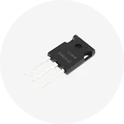
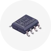
SCR silicon controlled rectifier circuits are of various types depending on the application. Some operate by triggering SCR for switching functions, while others employ SCR for phase control of AC power. Here is a list of the commonly available types of SCR silicon controlled rectifier circuits:
Phase Control Circuits
This type of SCR circuit controls AC power by adjusting the phase angle of the SCR conduction. Here the SCR is triggered to conduct at a particular phase angle, controlling the average power delivered to the load. These circuits are commonly used in dimmers, motor speed controls, and heating equipment, where gradual control of the power is required. The ability to adjust power levels without rapidly switching on/off makes phase control circuits suitable for various applications requiring fine control over time.
Chopper Circuits
DC chopper circuits are used to control the output voltage and power in DC systems by periodically triggering SCRs to convert DC power levels. One SCR can serve as a switch to connect or disconnect the load from the DC source, while others can be used to alternate the output voltage levels by adjusting the firing angles. Chopper circuits are applied in adjustable power supplies for industrial processes, battery chargers, and electric vehicles where controlled power delivery.
Inverter Circuits
These circuits convert DC to AC power using SCRs. SCRs are arranged in a bridge configuration to produce an alternating output voltage. Inverter circuits are used in applications such as uninterruptible power systems (UPS), renewable energy systems (solar, wind), and variable frequency drives (VFD) for motor control. In these situations, converting power is needed, and the capacity to produce an output waveform for AC applications makes SCR inverter circuits an essential for various energy applications.
Phase-Locked Loop (PLL) Circuits
The PLL circuits regulate the output voltage or frequency by controlling the triggering of SCRs. These circuits are used for stabilizing voltage levels in power systems and ensuring that the generated AC frequency matches a desired reference value. SCRs are triggered based on error signal feedback, which indicates the discrepancies between the output and reference parameters. PLL circuits are utilized in synchronous inverters, frequency converters, and power grid synchronization, where precise control and matching of voltage and frequency are crucial for system stability and performance.
Tiristor-Only Inverter
As the name suggests, these are inverter circuits solely employing SCRs (thyristors) to convert direct current into alternating current. Typically, four SCRs are arranged in a configuration called a thyristor bridge. During the positive half cycle, two SCRs (let's call them TH1 and TH2) conduct outgoing DC and produce AC output. Inverter circuits are used in UPS, electric vehicle power supplies, and off-grid AC power generation.
The durability of SCR silicon controlled rectifier circuits is a factor of their material composition. SCRs are designed for reliability in various demanding environments. Key elements that impact their robustness are thermal management, and heat sinks, for instance. The construction of SCRs involves the following elements:
Silicon
Usually, silicon is the primary semiconductor material used in SCRs. Silicon-based SCRs offer robustness and thermal stability in SCR silicon controlled rectifier circuits. Silicon has excellent electrical properties, hence allowing efficient control of high-voltage and high-current loads. Silicon's ability to withstand high temperatures and retain mechanical strength makes SCRs durable in industrial and commercial environments.
Doping Elements
Doping elements such as phosphorus and boron are added into silicon to create N-type and P-type regions within the SCR. This combination forms the P-N-P-N structure that enables thyristor functionality. Commonly used doping materials are epitaxial growth, ion implantation, and diffusion, ensuring precise control over electrical conductivity. Such enhanced conductivity guarantees durability and excellent performance under high power and thermal stress.
Electrode Materials
The SCR silicon controlled rectifier circuits are equipped with electrodes for efficient conduction of electric current. Typically, these electrodes are made of alloyed metals, usually with good electrical conductivity. This material ensures minimal voltage drop, reduced heat generation, and effective power transmission. Commonly, the electrodes are designed for corrosion resistance and long-term reliability under dynamic loads.
Heat Sink Design
Heat sinks are integrated into SCR circuits to maximize durability through effective heat dissipation during operation. The heat sink is typically made from aluminum or copper, with high thermal conductivity to rapidly dissipate generated heat. Owing to its lightweight and efficient processes, aluminum is used in many applications, while copper is predominant in high-power applications due to its superior heat transfer capabilities. SCR circuits ensure longevity by preventing overheating through robust heat sink designs.
Enclosures
Generally, enclosures are designed for SCR circuits, protecting against environmental elements like dust, moisture, and chemical exposure. Common materials are steel or aluminum alloys with anti-corrosive coatings. These enclosures provide structural integrity and enhance the longevity of SCR circuits in demanding industrial settings. Steel offers rugged protection for heavy-duty applications, while lightweight aluminum enclosures are favored in mobile or space-constrained environments.
SCR silicon controlled rectifier circuits have wide-ranging industrial, renewable energy, and motor control applications. Their ability to switch and control high voltages and currents makes them ideal for the following scenarios:
Industrial Motor Drives
Typically, these drives control the speed and torque of large AC and DC motors by regulating power delivery. Controlled rectifiers manage the application of electrical energy to motors, facilitating precise speed control in manufacturing, pumping, and conveyor systems. By varying output power, businesses can operate motors efficiently under different loads, reducing energy consumption and extending equipment life.
HVDC Transmission Systems
In these systems, controlled rectifiers are used to convert alternating current to direct current for long-distance power transmission. SCRs help minimize transmission losses over vast distances, making the technology suitable for connecting remote energy sources or stabilizing power grids. This efficiency enables economic transport of electricity, especially from renewable sources like wind and solar farms.
Power Supplies
Here, controlled rectifiers convert AC to DC power, providing stable voltage levels for electronic equipment. They are essential in industrial applications where large quantities of power are consumed, maintaining system stability and preventing damage from voltage fluctuations. Utilizing SCRs enables capacity power supplies to support critical operations requiring continuous power availability.
Renewable Energy Systems
In these systems, SCRs manage energy conversion processes. For solar systems, they convert the DC generated by solar panels into AC for grid injection or local consumption. Wind power utilizing variable-speed turbines employs controlled rectifiers to extract maximum power by adjusting the operating point. SCRs ensure efficient energy capture and delivery, promoting the effectiveness of renewable technologies.
Electrochemical Processes
SCR-controlled rectifiers are utilized in industries such as metal electroplating, chemical production, and battery charging. Here, precise DC current control is required to maintain product quality and chemical reaction rates. In electroplating, for instance, current variations affect metal deposition, influencing surface finish and coating thickness. SCRs enable fine current adjustments, leading to better process outcomes and increased production efficiency.
When selecting SCR silicon controlled rectifier circuits, factors such as operational requirements, load characteristics, and environmental conditions should be considered. One needs to assess the key components and features that determine the performance and reliability decide the following:
Current Rating
The maximum operational current of SCR circuits should equal or exceed the expected load current. This prevents overheating and ensures system stability. Conversely, an excessively high current rating may reduce efficiency. Properly matching the current rating to the application demands guarantees optimal performance without compromising the reliability of the components.
Voltage Rating
Typically, voltage ratings should handle peak reverse voltage in AC applications or steady-state DC voltage in rectifier circuits. This avoids breakdown and circuit failure. It is crucial to consider transients and surges, which may momentarily exceed normal operating conditions. Select circuits with adequate spacing between rated voltages and operating conditions for added safeguard against unexpected voltage spikes.
Firing Angle Control
If precise power control is essential in an application, look for circuits with adjustable firing angle. This determines the point of SCR conduction within an AC cycle, enabling control over the delivered power. Such flexibility is useful for applications like motor speed regulation or lamp dimming, where gradual power adjustment is vital for process requirements.
Heat Dissipation and Management
In high-power applications, heat generation could impact the reliability of SCR components. Therefore, consider SCR circuits with effective heat sinks or cooling mechanisms. Aluminum or copper-based heat sinks rapidly dissipate generated heat to maintain optimal operating temperatures. Additionally, good thermal management protects against overheating and prolongs the lifespan of SCR circuits in demanding environments.
Load Types
AC or DC load types should reflect the choice between the circuits and what mode of control is applicable to the load. For instance, a circuit with controlled rectifiers is suitable for DC applications, while those with a triac are ideal for AC loads. Considering the load nature ensures that the selected circuit operates efficiently without causing excessive stress to the components, which in turn increases reliability.
Turn-Off Time
Usually, turn-off time defines how fast the SCR can stop conducting after receiving a gate signal. This parameter becomes critical in dynamic loads requiring rapid power adjustments. Here, applications like electric furnaces or induction heating need shorter turn-off times to enable quick on/off power cycling. Conversely, in steady-state processes, longer turn-off times are tolerable.
A1: SCR circuits with adjustable firing angles are applied to power control in industrial motor drives, electroplating, and chemical processing. They finely regulate motor power during heavy industrial duties and electroplating baths, which require controlled currents and voltages for even metal deposition in a chemical factory.
A2: The materials forming the SCR structure are heat resistant and thermally stable, with excellent mechanical strength, able to withstand high temperatures without losing their integrity. Moreover, effective heat sinks for dissipating generated heat help maintain optimal operating temperatures, contributing to overall reliability.
A3: SCR silicon controlled rectifier circuits stabilize voltage levels in power supplies within electric vehicles. They control power delivery to the vehicle's electric motor and other systems, maintaining consistent performance even when battery voltage fluctuates. This ensures the vehicle functions reliably despite varying loads and operating conditions.
A4: Yes, SCR circuits featuring controlled rectifiers are suitable for electric vehicle applications, mainly to stabilize power supply voltage levels. Therein lies their ability to maintain system reliability by providing consistent voltage, allowing electric vehicles to perform various functions such as powering the motor and other electronic systems reliably.
A5: Considerations include the electrical characteristics of the operating conditions, the load type, and the environmental factors. One must ensure the turn-off time and current-handling capacity are sufficient for the intended application. Comparing various products, one should assess the operating voltage, where the product must accommodate the electrical system voltage to prevent circuit failure.