All categories
Featured selections
Trade Assurance
Buyer Central
Help Center
Get the app
Become a supplier
(876 products available)
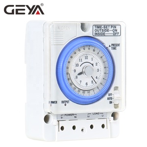


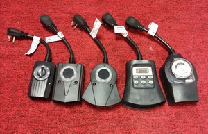


As a rule, several variants of Timer Switch Circuit Diagram can be found in the electrical equipment market. These common diagrams serve various clients' operational requirements and convenience. Therefore, understanding the different models on offer is crucial.
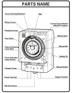
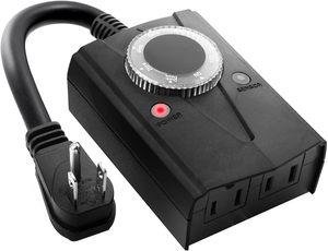
The operational control of various devices is often done using the analog timer switches. Their effectiveness is attributed to a rotating dial that keeps time. These circuits run on simple mechanics, and there is usually a set period for turning a device on and off.
This system is best applied when prolonged and regular tasks need to be done and when device control is needed depending on time schedules.
These are primarily used for high-accuracy control. The key thing about this variant is that it uses a microcontroller with a digital LCD screen. This sophistication allows its user to set more complex timing sequences, like turning systems on at one point and off at another, in a particular weekly schedule.
This system is suitable for HVAC systems or pool pumps where such operational needs exist. It is mostly found where accuracy is more important than needs, such as in industries.
This timer switch uses a mechanical clockwork mechanism to drive the operations. Users appreciate the durability of this switch; thus, it is ideal when reliability is the crucial factor. In most cases, mechanical timer switches are used in heavy-duty environments, for instance, to control motors and other huge machines.
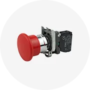
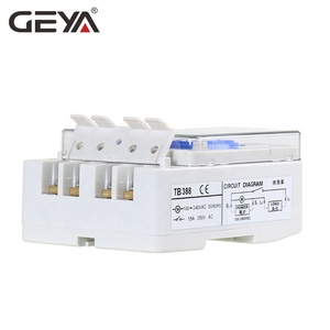
Timer switches based on relays are effective in low voltages. They utilize an electromagnetic relay in operation. The function of this relay is to connect/disconnect an electrical circuit based on the timer's status.
This timer switch is often needed in home automation systems, such as controlling lights or outlets. The beauty of relay switches is that they can be easily integrated with other electronic systems.
The success of switch timers is highly dependent not only on the designs but also on the materials and parts used. These components ensure the durability and reliability of the systems, particularly in industrial or commercial operations.
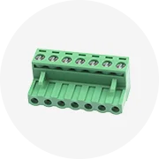
Material choice is important for terminals and connectors due to the potential risk of voltage variances and the need of making tight connections to prevent electrical arcing. Gold-plated and silver contacts offer great electrical conductivity and corrosion resistance, thus ensuring low resistance over time.
Copper with tin has good conductivity and is cost-effective for non-critical applications. However, over time tin can oxidize, resulting in poor connections. The terminals and connectors are designed with the following materials: copper, gold-plated, or silver, which enhance conductivity and resist the Timer Switch Circuit Diagram.
Printed circuit boards (PCBs) for the Timer switches are primarily made from fiberglass epoxy resin (FR-4). The material is not only durable, but also resistant to heat, so it doesn't warp or lose the electric connection when the temperature changes frequently.
For high-end switches, a PCB is based on ceramic material. This option is great because its thermal conductivity aids in better heat dissipation. Additionally, gold-plated PCBs are used in areas where one needs superior performance and reliability, although they are not cost-effective.
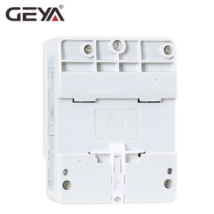
The casing of the timer switches protects internal parts from dust, moisture, and mechanical damage. Polycarbonate enclosures are used because of their high impact resistance and good transparency. ABS enclosures balance strength and rigidity at lower costs.
Steel enclosures are more preferred in harsh environments because they provide more than average protection against mechanical damage and electromagnetic interference (EMI). Moreover, stainless steel housings are employed in configurations where timer switches are exposed to corrosive substances.
Many timer switches are designed with temperature sensors, proximity sensors, or humidity sensors to improve their functionality. Temperature sensors are made from materials like thermocouples, copper, and nickel.
This copper and nickel combination has high durability and conductivity to temperature changes. Proximity sensors use inductive/capacitive sensors with metal components such as copper or aluminium. Many proximity sensors come with weather protection made of silicon plastic materials.
Humidity sensors are normally made of polymeric capacitor materials. These materials change their capacitance in response to moisture levels. Thus, selection of materials for sensors in a Timer Switch Circuit Diagram determines functionality and durability.
The Timer Switch Circuit Diagrams have immense applications in various commercial operations. These uses identified largely and known to all enhance system productivity and offer an effective way of controlling tasks.
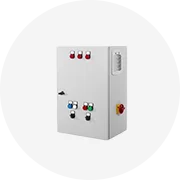
In industrial enterprises, Timer switches control machinery and production lines. It is critical in the manufacturing process to ensure that machines work within the prescribed cycle time. This helps in reducing human error and optimizing operations.
Timer switches ensure operations run with minimal distress, thus labeled the machines have longer life and productivity is enhanced. The Timer Switch Circuit Diagrams are used widely in industrial explosion-proof casings and waterproofs, hence perfect for use in the industrial environment.
Heating, ventilation, and air-conditioning systems extensively use timer switches for effective operation and energy consumption. Switches regulate when units should operate depending on time, which means no wastage of energy when cooling or heating spaces.
That is to say, the circuit diagrams help in controlling air handlers and compressors to ensure they operate at the right times. It is particularly important for large commercial buildings that need good management of their climate control systems.
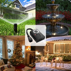
Timer switches control lighting systems in commercial applications, such as in offices and retail stores. For instance, in a retail store, lighting switches help in setting up the store lighting to go on and off at preset hours.
This saves energy when the store is closed after work and ensures the store is well lit during working hours. Furthermore, Timer Switch Circuit Diagrams control outdoor lighting systems, enabling them to be lit continuously after sunset and extinguished after sunrise.
Timer switches are employed in pool and spa systems to manage filtration, heating, and cleaning cycles. Basically, switches help in setting up these cycles to run optimally, ensuring water quality in pools and spas stay good.
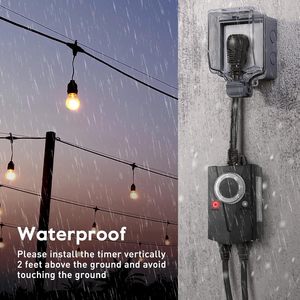
This prolongs the equipment's life and lowers the cost of energy by preventing filtration and heating from operating all the time. In this case, Timer Switch Circuit Diagrams are sealed in waterproof enclosures, so they are suitable for use in this environment.
There are several factors one should consider when choosing timer switch Circuit Diagrams for clients. Clients will have different uses of the switches, which makes these switches suitable for various applications.
Selecting the right timer switch depends heavily on timing accuracy. For example, clients who need basic on-and-off cycles for their devices can be served well with an analog or mechanical timer. In contrast, those who need precise control must go for digital timers that will allow detailed programming.
The load capacity of the Timer Switch Circuit Diagrams must be the same as that of the application they are used in. A switch that has a high load capacity should be selected for increasing electrical loads, like machinery in industrial plants.
On the other hand, lower load switches should suffice in lesser environments like office lighting or small HVAC systems. Choosing a switch that meets the operational needs properly and ensures client safety avoids overloading and switch failure.
For clients whose applications involve extreme working conditions, go for Timer Switch Circuit Diagrams built to resist environmental factors. Strong protective enclosures are needed for installations involving dust, moisture, or chemicals. Moreover, in environments where temperature variations are extreme, prefer switches with heat-resistant inner components.
How easy the timer switch will be installed in the client's systems is another factor to consider. For clients with multiple systems where uniformity is required, go for those easily programmable and offer a common interface. Moreover, ensure compatibility with the existing equipment in the system.
The Timer Switches are critical in controlling electrical loads based on predetermined schedules in any energy management system. They minimize energy wastage by ensuring systems operate only when needed and then turning off during off-peak times.
These timer switches can control lighting and outlets reliably and are low-voltage friendly. In addition, they are easy to incorporate into other monitoring and control circuits.
Enclosures made of stainless steel or polycarbonate, coupled with internal heat-resistant components, ensure that timer switches endure severe conditions and last longer.
The application's timing accuracy requirement will determine the most appropriate timer switch. A digital switch may be needed for precise control, while an analog switch would adequately meet the needs of simple tasks.