
Diodes are essential components in electronic circuits, allowing current to flow in one direction while blocking it in the reverse. When a circuit malfunctions, a faulty diode is often a suspect. Accurately testing a diode with a multimeter ensures you can diagnose issues quickly and avoid unnecessary replacements. This guide walks through the process methodically, ensuring consistent and trustworthy results every time.
Understanding Diode Basics Before Testing
A diode has two terminals: the anode (positive) and cathode (negative). In normal operation, it conducts current when forward-biased (positive voltage applied to the anode) and blocks current when reverse-biased. A healthy diode will show low resistance in one direction and high resistance in the other. If it conducts in both directions or neither, it's likely damaged.
Different types of diodes—such as standard silicon, Schottky, Zener, and LEDs—behave slightly differently under test. Silicon diodes typically show a forward voltage drop between 0.5V and 0.8V. Schottky diodes have lower drops (0.15–0.45V), while LEDs range from 1.8V to 3.3V depending on color and material.
“Testing diodes properly separates competent troubleshooting from guesswork.” — Dr. Alan Reeves, Electronics Diagnostics Lab Manager
Preparing Your Multimeter and Workspace
Before testing, ensure your multimeter is functional and set up correctly. Use a digital multimeter (DMM) with a dedicated diode test function, usually indicated by a diode symbol (▶|—). This mode applies a small voltage to the component and measures the resulting forward voltage drop.
If your meter lacks a diode setting, use the resistance (ohms) mode, though this method is less accurate and may not activate the diode junction properly.
- Inspect probe insulation for cracks or wear.
- Replace weak batteries—low power affects accuracy.
- Clean the diode leads with isopropyl alcohol if corroded.
- Work on an anti-static mat when handling sensitive components.
Step-by-Step Guide to Test a Diode with a Multimeter
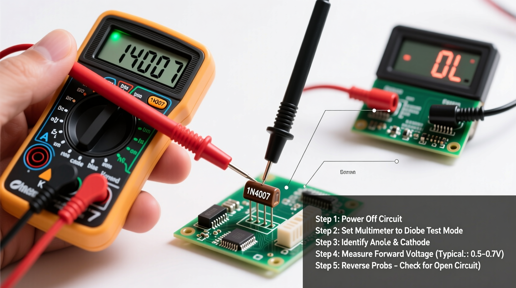
- Power off and discharge the circuit. Unplug any device and safely discharge capacitors to prevent shock or damage.
- Remove the diode from the circuit board. Soldering it out prevents false readings from parallel components.
- Set the multimeter to diode test mode. Rotate the dial to the diode symbol. The display should show \"OL\" or \"1\" when probes are open.
- Identify the diode’s cathode. Look for a band, stripe, or notch on the body—it marks the cathode end.
- Test in forward bias. Place the red probe on the anode and the black on the cathode. A good silicon diode reads between 0.5V and 0.8V.
- Reverse the probes for reverse bias test. Move red to cathode, black to anode. The display should show \"OL\" or \"1\", indicating no conduction.
- Interpret the results:
- Forward reading: 0.5–0.8V → Normal (silicon)
- Reverse reading: \"OL\" → Good isolation
- Both directions show \"OL\" → Open diode (failed)
- Both directions show low voltage → Shorted diode
- Near 0V forward → Possible short
- 0.2–0.3V forward → Likely Schottky type
Special Cases: Testing Zener and LED Diodes
Zener diodes are designed to conduct in reverse at a specific breakdown voltage. Standard diode test mode won’t reveal this without additional circuitry. However, you can still verify forward conduction (0.5–0.7V) and check for shorts.
For LEDs, the forward voltage varies by color:
- Red: ~1.8V
- Green: ~2.2V
- Blue/White: ~3.0–3.3V
Common Mistakes That Lead to False Readings
Even experienced technicians can misdiagnose diodes due to procedural errors. Avoid these common pitfalls:
| Mistake | Consequence | Solution |
|---|---|---|
| Testing in-circuit without isolation | Parallel components skew readings | Desolder at least one lead before testing |
| Using ohmmeter instead of diode test | Inconsistent bias voltage, misleading values | Use diode test mode when available |
| Reversing probe polarity incorrectly | Misidentifying anode/cathode | Double-check band marking on diode body |
| Ignoring temperature effects | Voltage drop decreases as temperature rises | Test at room temperature; avoid heated environments |
| Assuming all diodes behave like silicon | Misreading Schottky or germanium drops | Know expected Vf based on diode type |
Real-World Example: Diagnosing a Power Supply Failure
A technician was called to repair a wall-mounted router that wouldn’t power on. Initial inspection showed no blown fuses or visible burns. Using a multimeter, they tested the input bridge rectifier—a four-terminal assembly made of four internal diodes.
After desoldering one corner, they performed individual diode checks across each pair. Three legs showed proper forward voltage (~0.6V) and open reverse. One leg, however, conducted equally in both directions—indicating a shorted diode inside the bridge.
The entire bridge was replaced, restoring full functionality. Had the technician relied solely on voltage measurements at the output, they might have wasted time chasing non-existent regulator faults. Direct diode testing pinpointed the root cause efficiently.
Essential Checklist for Reliable Diode Testing
Follow this checklist every time you test a diode to ensure consistency and accuracy:
- ✅ Power down and discharge the equipment
- ✅ Remove the diode from the circuit (at least one lead)
- ✅ Verify multimeter battery strength
- ✅ Select diode test mode (not resistance)
- ✅ Identify cathode via physical marking
- ✅ Measure forward voltage drop (red to anode)
- ✅ Measure reverse bias (red to cathode)
- ✅ Compare results against expected values
- ✅ Record findings for future reference
Frequently Asked Questions
Can I test a diode without removing it from the circuit?
You can, but results may be inaccurate due to parallel resistances or semiconductor paths. For definitive diagnosis, isolate the diode by removing at least one terminal from the PCB.
Why does my multimeter show \"OL\" in both directions?
This indicates an open diode—one that has failed and no longer conducts in either direction. It must be replaced. Confirm by checking connections and trying another known-good diode.
Is a 0.4V forward reading always bad?
No. While typical silicon diodes read 0.5–0.8V, Schottky and germanium diodes naturally have lower drops (0.15–0.4V). Know your component type before concluding failure.
Final Thoughts and Next Steps
Accurate diode testing is a foundational skill in electronics maintenance and repair. By following a disciplined approach—using the correct multimeter settings, isolating components, and interpreting results wisely—you gain confidence in your diagnostics. Whether you're repairing consumer electronics, automotive systems, or industrial controls, mastering this simple procedure saves time, reduces costs, and improves reliability.


 浙公网安备
33010002000092号
浙公网安备
33010002000092号 浙B2-20120091-4
Comments
No comments yet. Why don't you start the discussion?