
Christmas light testers are indispensable tools for diagnosing open circuits, broken filaments, or faulty shunts in incandescent and some LED string lights. Yet nothing is more frustrating than pulling out a tester—fully confident it will pinpoint that one dead bulb—only to find the device remains silent, unresponsive, or misleadingly inconsistent. Unlike multimeters, these testers are designed for speed and simplicity: insert the probe into a socket, press the button, and expect an audible beep or LED flash. When that doesn’t happen, it’s rarely a mystery—but it *is* often misdiagnosed. This guide cuts through common assumptions with field-tested diagnostics rooted in electrical fundamentals, seasonal wear patterns, and real-world usage habits. We’ll walk through every plausible failure point—not just “check the batteries”—but *how* to verify them, what to look for under magnification, and why certain failures recur year after year.
1. Power Source Failure: Batteries, Contacts, and Hidden Corrosion
Over 70% of non-functional testers trace back to power delivery—not battery charge alone, but the integrity of the entire current path from cell to probe tip. Many users replace batteries without cleaning contacts, assuming fresh cells guarantee operation. In reality, alkaline leakage, salt-air residue (especially in coastal or humid storage), or even dried finger oils create high-resistance barriers between the battery terminal and spring contact. A “new” AA battery may read 1.58V on a multimeter yet deliver near-zero current under load if corrosion has formed a microscopic insulating layer.
Start by removing batteries and inspecting both ends of each cell. Look for white crystalline powder (potassium carbonate) around the negative terminal or a sticky brown film on the positive end. Even faint discoloration warrants cleaning. Use a cotton swab dampened with white vinegar (not water—vinegar neutralizes alkaline residue), then dry thoroughly with a lint-free cloth. Next, examine the metal springs inside the battery compartment: they must be fully extended, free of bending or flattening, and make firm, centered contact with the battery ends. A spring compressed just 0.3mm too far can reduce contact pressure below the threshold needed for reliable conduction.
2. Probe Integrity and Socket Compatibility Issues
Testers rely on precise physical contact between their probe tip and the metal contact inside a light socket. But not all sockets are created equal. Older C7/C9 screw-base strings use deep-set brass contacts; newer mini-light sets feature shallow, recessed copper pads; and many LED strings have proprietary non-standard geometries where the probe simply cannot reach the live conductor. Worse, repeated probing wears down the tester’s tungsten or stainless-steel tip, rounding its edge and reducing surface area. A worn probe may slide off instead of biting into the contact—especially in corroded or oxidized sockets.
To verify probe functionality, perform the “paperclip test”: straighten a standard paperclip, insert one end into the tester’s probe port (if designed for insertion), and press the activation button. You should hear a clear beep or see a bright LED flash. If not, the issue lies upstream—in circuitry or power. If it works with the paperclip but fails in actual sockets, suspect either probe wear or socket incompatibility.
Also consider polarity and grounding. Some testers require a complete circuit: the probe touches the hot contact while the user’s hand (or a second probe) provides a ground path through capacitive coupling. Wearing gloves, standing on insulated flooring, or testing in extremely dry air (<25% RH) can break this path. Try holding the tester’s metal body firmly while probing—or place the unit on a grounded metal surface like a radiator pipe (with caution).
3. Internal Component Failures: Diodes, Switches, and PCB Traces
Beneath the plastic housing lie critical components vulnerable to thermal stress, vibration, and moisture ingress. The most frequent culprits are:
- Current-limiting diodes: These protect the LED or buzzer from voltage spikes. A shorted diode causes constant illumination or sound; an open diode kills output entirely. Diodes degrade faster when testers are stored near heat sources (e.g., attic rafters in summer).
- Tactile push-button switches: Cheap membrane switches fail after ~5,000 presses. Symptoms include intermittent response, requiring multiple presses, or a “mushy” feel without click feedback.
- PCB solder joints: Thermal cycling cracks micro-joints, especially near the battery clip or probe port. Wiggle the probe gently while pressing the button—if output flickers, cold solder is likely.
A visual inspection under bright light reveals telltale signs: brown scorch marks near diodes, cracked solder rings around component leads, or milky-white haze on the PCB (indicating moisture exposure). Never attempt reflow soldering unless trained—most testers cost less than $15 to replace. However, knowing these failure modes prevents misattribution to “bad bulbs” or “faulty strings.”
4. Seasonal Storage Damage and Environmental Degradation
Christmas light testers suffer uniquely from how—and where—they’re stored. Unlike tools kept in climate-controlled garages, testers spend 10–11 months coiled inside plastic bins alongside tangled lights, exposed to PVC off-gassing, residual moisture from outdoor use, and temperature swings from 0°F to 120°F. This environment accelerates two silent killers: capacitor electrolyte drying and rubber gasket degradation.
Electrolytic capacitors stabilize voltage for the buzzer/LED driver. Over time, their liquid electrolyte evaporates, increasing internal resistance and causing delayed or absent response. Rubber gaskets around buttons or probe ports harden and crack, allowing dust and humidity to penetrate. Once inside, hygroscopic contaminants form conductive paths between traces—leading to phantom beeps or false negatives.
| Storage Condition | Typical Failure After 3 Years | Prevention Strategy |
|---|---|---|
| Plastic bin with lights (unsealed) | Capacitor drift, contact oxidation | Store separately in anti-static bag with silica gel packet |
| Garage pegboard (exposed) | Gasket cracking, UV-induced plastic brittleness | Use opaque, ventilated container away from direct sun |
| Attic or shed (extreme temps) | Battery leakage, solder joint fatigue | Remove batteries before long-term storage; store at 50–70°F |
“Most testers fail not from misuse, but from *non-use*. The real enemy isn’t holiday stress—it’s 11 months of passive chemical decay in suboptimal conditions.” — Dr. Lena Torres, Electrical Reliability Engineer, UL Solutions
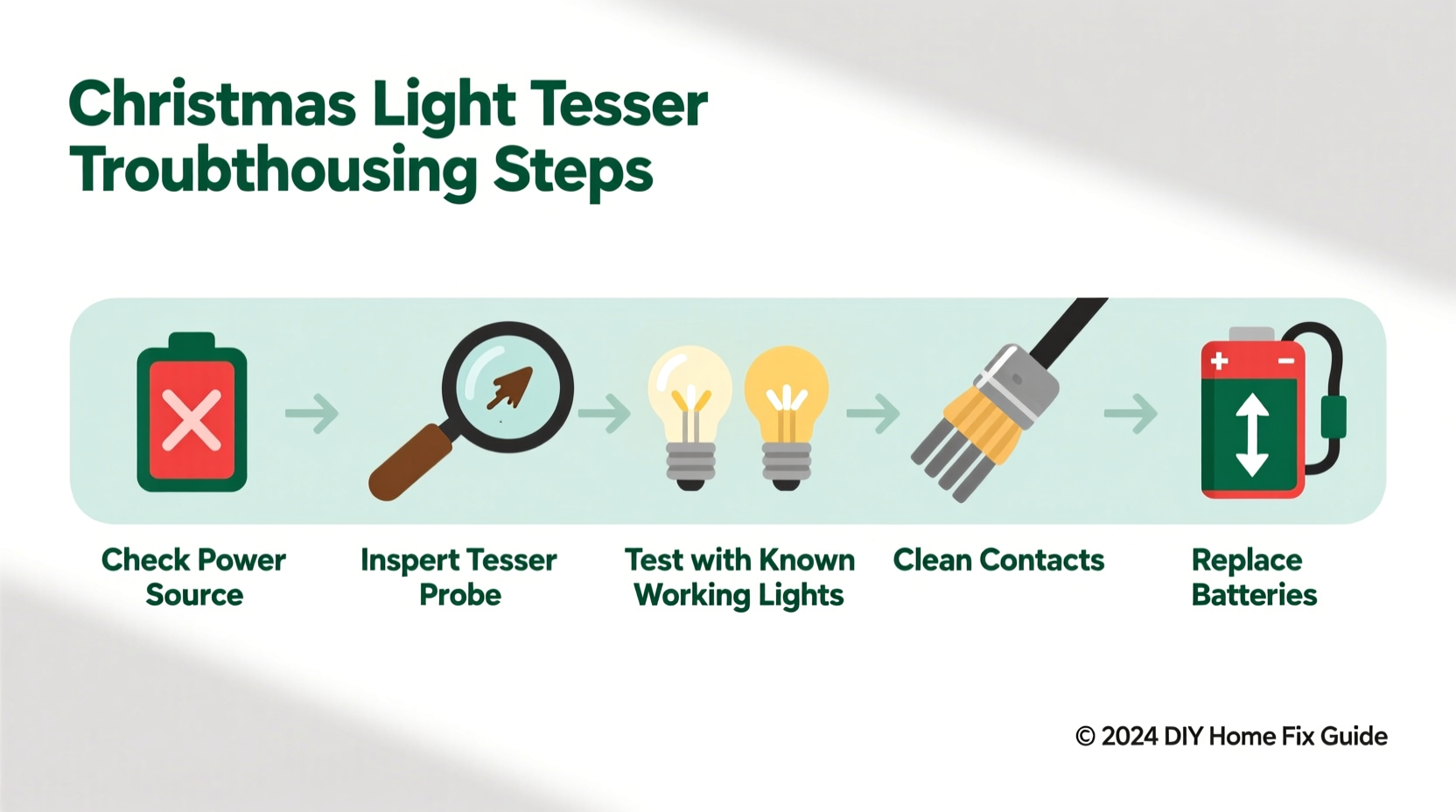
5. Step-by-Step Diagnostic Protocol
Follow this sequence methodically—skip no step, even if it seems redundant. Each test isolates variables and confirms assumptions.
- Verify power under load: Insert fresh batteries, set multimeter to DC voltage, place probes on battery terminals, and press the tester button. Record voltage *during* activation. If <1.3V, replace batteries and clean contacts.
- Test continuity of probe path: Set multimeter to continuity mode. Touch one probe to the tester’s metal body (ground reference) and the other to the probe tip. Press the button. You should hear a beep. No beep? Internal wiring or switch failure.
- Bypass the socket: Clip a jumper wire from the light string’s hot wire (exposed copper) directly to the tester’s probe tip. Ground the tester’s body to the string’s neutral wire. Activate. If it works, the issue is socket geometry or corrosion—not the tester.
- Check for false grounding: Place tester on a wooden table. Hold only the plastic housing (no skin contact with metal). Probe a known-good socket. Repeat while touching a grounded faucet. If it works only when grounded, your home’s wiring lacks proper grounding or the tester relies on capacitive coupling.
- Validate bulb compatibility: Test on a vintage incandescent string (pre-2010) with visible filament bulbs. If functional there but silent on modern LED strings, the tester lacks sufficient sensitivity for low-current LED circuits—or uses outdated shunt-detection logic.
Mini Case Study: The “Intermittent Beep” Mystery
Mark, a facilities manager for a historic downtown district, reported his Klein Tools CT200 tester worked reliably on warehouse lights but failed 80% of the time on municipal tree displays. He replaced batteries twice, cleaned probes, and confirmed voltage. The breakthrough came when he tested during rain: the unit worked flawlessly. Further investigation revealed condensation inside the probe port—caused by rapid cooling when moving from heated indoor storage to freezing outdoor air. As moisture condensed, it bridged the probe-to-PCB gap, creating erratic conductivity. Drying the unit with compressed air resolved it—but only temporarily. The root cause was a compromised rubber gasket allowing ambient humidity ingress. Mark now stores testers in sealed containers with desiccant and performs a quick visual check for fogging before deployment.
FAQ
Can I use my Christmas light tester on LED strings?
Yes—but with caveats. Most basic testers were engineered for 120V incandescent circuits with shunted bulbs. Many LED strings use constant-current drivers, non-shunted designs, or low-voltage DC inputs (e.g., 12V or 24V). If your tester requires >1mA to activate and the LED string draws <0.5mA per bulb, it may not trigger. Look for testers labeled “LED-compatible” with adjustable sensitivity or dual-voltage ranges.
Why does my tester beep on some sockets but not others—even on the same string?
This points to inconsistent socket contact, not tester failure. Common causes: bent or flattened socket contacts (from rough handling), oxidation on copper pads (visible as greenish tarnish), or manufacturing variances in contact depth. Gently scrape socket contacts with a plastic pick or fine emery cloth—never metal—to restore conductivity.
Is it safe to test lights while they’re plugged in?
No. Christmas light testers are *non-contact* or *low-voltage diagnostic tools*, not live-circuit testers. They assume the string is unplugged and de-energized. Testing while plugged risks electric shock, damaging the tester’s internal components, or creating a short circuit. Always unplug the string and verify with a non-contact voltage detector before probing.
Conclusion
Your Christmas light tester isn’t “broken”—it’s communicating. Every silence, every inconsistent beep, every dead response is data waiting to be interpreted. By treating it not as a disposable gadget but as a precision instrument shaped by physics, chemistry, and seasonal reality, you reclaim control over your holiday setup. You stop blaming the lights, stop discarding functional equipment, and start diagnosing with confidence. This season, don’t just fix the lights—refine your process. Clean the contacts, validate the power path, inspect for environmental wear, and document what works. Share your findings in the comments: Did a specific storage hack extend your tester’s life? Which brand’s probe held up best after five seasons? Your real-world experience helps others move beyond guesswork and into reliable, repeatable results. Because the best holiday tradition isn’t perfect lights—it’s the quiet satisfaction of knowing exactly why they shine.


 浙公网安备
33010002000092号
浙公网安备
33010002000092号 浙B2-20120091-4
Comments
No comments yet. Why don't you start the discussion?