All categories
Featured selections
Trade Assurance
Buyer Central
Help Center
Get the app
Become a supplier
(4175 products available)

 Ready to Ship


 Ready to Ship


 Ready to Ship
There are several types of PWM circuits for DC motors, each with varying levels of complexity and control capabilities. The choice of PWM circuit depends on factors such as the required speed range, the load on the motor, and the desired efficiency. Below are the main types:
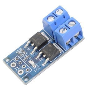
Simple PWM Controller
A simple PWM controller is a basic circuit that uses a transistor or MOSFET to switch the DC motor on and off rapidly. This type of controller is straightforward and inexpensive and is commonly used in low-power applications. However, simple controllers usually have limited speed control and may generate more heat and less efficient than advanced circuits.
555 Timer-Based PWM
PWM controllers using a 555 timer are more versatile than simple controllers. The 555 timer allows the user to adjust the duty cycle with a variable resistor. This provides more precise speed control. It is a cost-effective solution for medium-power applications, but it is less efficient than microcontroller-based designs.
Microcontroller PWM
Microcontroller-based PWM circuits are more complex but offer greater control over motor speed and direction. By using a microcontroller, the duty cycle can be adjusted based on input from sensors or user commands. This is to enable closed-loop control systems. These circuits are ideal for high-precision applications but are more expensive and require programming knowledge.
H-Bridge PWM Controllers
An H-bridge controller is a circuit that uses transistors or MOSFETs configured to drive a DC motor. This is while allowing for bidirectional control of the motor. The H-bridge circuit can control motor direction and speed by varying the duty cycles of the two PWM signals. It is widely used in robotics and mobile applications for its versatile capabilities.
Analog PWM Controller
An analog PWM controller is a circuit that generates a PWM signal using operational amplifiers and comparators. This type of controller is highly customizable and can be designed to handle a wide range of voltages and currents. Analog controllers are preferred in specialized applications requiring more precise control than digital circuits.
PWM circuits for DC motors are widely used in various industries. This is because of their ability to control motor speed efficiently. Below are key industrial applications:
Automation and Robotics
In automation, microcontroller PWM circuits control high-precision DC motors in robotics. PWM circuits regulate the motor speed and direction. It this allows robots to perform tasks like assembly, painting, or welding with precision. They also enable the development of closed-loop systems that adjust motor performance based on feedback. This enhances the overall efficiency and accuracy of robotic operations.
Automotive Applications
PWM controllers are commonly used in vehicles to control various features powered by DC motors. They include power windows, seat adjusters, and cooling fans. For instance, using a 555 timer IC for a simple PWM circuit can adjust the fan speed based on engine temperature. This is to optimize airflow and prevent overheating. PWM control helps extend the motor's lifespan by reducing energy consumption and wear.
HVAC Systems
In HVAC systems, PWM circuits control motors in fans and blowers to regulate airflow and achieve desired temperature settings. This is particularly useful with variable-speed fans, as PWM enables smooth motor speed transitions per the cooling or heating needs. It reduces energy consumption by maintaining optimal motor speeds. This lowers electricity costs and decreases wear on motor components.
Conveyor Systems and Heavy Machinery
PWM circuits are used in heavy machinery and industrial conveyor belts in manufacturing plants. They control the speed of motors running conveyor belts, lifts, and other heavy equipment, ensuring precise operation. PWM controllers allow the adjustment of motor speeds to match the material handling requirements. This impacts productivity and the lifespan of the equipment.
Aerospace Systems
In aerospace applications, PWM controllers regulate the speed of actuators and small DC motors in control surfaces, landing gear, and other subsystems. Due to the critical nature of aerospace operations, selecting the appropriate PWM circuit for the motor is vital for reliability and performance.
The PWM circuit for DC motors has the following features and specifications:
Key Features
The key features include:
How To Install
The installation involves the following steps:
Connect The Motor
After connecting the motor, the next step is to connect the motor to the PWM circuit. This is to ensure the PWM signal from the circuit is sent to the motor.
Testing
The final step is testing the installation. Turn on the power supply and adjust the variable resistor. Observe the motor to see if it responds correctly to the PWM signal. Check for proper speed control and direction. Also, ensure there are no overheating or instability issues.
Maintenance And Repair
Maintenance and repairs for PWM circuits include the following:
Testing
Repair the PWM circuit by testing it when a problem is suspected. Use a multimeter to check the voltage levels and ensure the circuit receives proper power. This helps identify any faulty components, such as the 555 timer or transistors. Replace the damaged ones to fix the problem properly.
Cooling System
The heat generated in the PWM circuit can damage it and even cause the DC motor to stop working. Ensure the circuit has adequate cooling, especially in high-power applications. Install heat sinks on key components or fans to dissipate heat effectively. Regularly inspect for overheating signs in circuits and motors.
The PWM circuit's proper use involves the following steps:
Duty Cycle Adjustment
Use a variable resistor to adjust the duty cycle of the PWM signal. A higher duty cycle means more power to the motor and faster RPM. A lower duty cycle means less power, resulting in a slower DC motor. The desired motor speed can thus be achieved by adjusting the duty cycle.
Load Consideration
Consider the load connected to the DC motor. Heavy loads require lower speeds with higher torque. Thus, a higher duty cycle is ideal for such cases. Conversely, lighter loads need higher speeds and lower torque. They call for a lower duty cycle to achieve that.
Feedback Monitoring
Monitor the motor's performance for applications requiring precise speed control. Use speed sensors or encoders to provide real-time feedback on the motor speed. This helps adjust the duty cycle dynamically to maintain the desired speed even under load variations.
Power Management
The PWM circuit manages battery or power supply usage effectively, particularly in portable devices. Maintain optimal duty cycles to minimize power consumption without sacrificing performance. This extends the overall operation time of the device using the DC motor.
Proper quality and safety measures for the PWM circuit for DC motors go a long way in ensuring reliable operations. Below are key quality and safety considerations:
Component Selection
Select high-quality components for the PWM circuit. They include the microcontroller, transistors, or MOSFETs. Ensure they can handle the motor's current and voltage requirements. This prevents component failure due to overheating or electrical damage. Inertial components work efficiently to ensure the overall system's reliability and performance.
Heat Management
Excess heat generation is one of the major problems in motor control circuits. It leads to component failure. Thus, to help prevent this, ensure adequate heat dissipation in applications requiring longer operational times. Use heat sinks on power transistors or MOSFETs to dissipate heat effectively. A fan may be needed to improve airflow in high-power applications.
Electrical Safety
Check the electrical connections frequently to ensure there are no exposed wires or short circuits. They pose a risk of electrical shock or fire. Use insulated tools when servicing the circuit to avoid electrical hazards. Proper grounding of the circuit helps to reduce the risk of electrical discharge.
Overcurrent Protection
Overcurrent can damage the components of the circuit and the motor itself. Integrate protective devices like fuses or circuit breakers. These help prevent overcurrent conditions by disconnecting the power supply when the current exceeds a certain threshold.
Moisture And Dust Protection
A PWM circuit for DC motors in a harsh environment is susceptible to moisture and dust. They affect its functionality and cause corrosion. Consider using enclosures to protect the circuit from environmental elements. The enclosure material choice allows heat dissipation while keeping dust and moisture out.
A1. A larger DC motor requires a PWM circuit with a higher current capacity. For this case, choose transistors or MOSFETs that can handle the motor's maximum current requirements. Larger motors may also require additional components, like heat sinks, to ensure proper heat dissipation during operation.
A2. Connecting a motor with a different voltage rating will lead to poor performance and maybe even damage the motor. A motor rated for a higher voltage will run inefficiently, drawing too much current and burning out. On the other hand, a motor rated for lower voltage will run slowly and may stall.
A3. The diode, known as the flyback diode, protects the PWM circuit from voltage spikes when the motor is turned off or switched off. These spikes can damage components in the circuit. The flyback diode provides a path for the motor's inductive kickback current to dissipate harmlessly.
A4. Yes, the PWM circuit can control multiple motors simultaneously. However, this requires that the circuit components can handle the cumulative current requirements of all the motors being operated at the same time.
A5. The duty cycle in the PWM circuit can be adjusted remotely using various methods. These include wireless modules like Bluetooth, Wi-Fi, or RF. It enables remote motor speed control. This is particularly useful in applications where motors need to be adjusted from a distance. They include robotics or outdoor machinery.